
Introduction to Castings
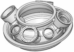
The turbine casing is a key component in the combustion chamber of a gas turbine. The turbine casing plays a role in forming a cavity for turbine operation, guiding the inlet and outlet air, supporting the turbine shaft, combustion chamber, and turbine rotating components, and increasing gas pressure. It is also a solid foundation for overall fixation. The maximum external dimension of the turbine housing Inches: 1780 mm x 1662 mm x 700 mm, weight 1.3 t. Due to the difficulty of production, the import price of each piece exceeds RMB 1 million, as shown in the 3D model of the turbine casing Our company has decided to independently produce a 3D model of the turbine shell from a manufacturer that can produce it.
Difficulties in casting process
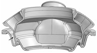
The turbine casing has a rotating body structure with multiple layers of thin-walled and narrow chambers. As shown in the sectional view, the arrow points to a narrow airway with a spacing of 65 mm, and most of the wall thickness is only 20 mm. The airway is only connected by the bottom, and the upper part is in an open state, which is very easy to deform. The inner surface of the airway is required to be free of defects such as sand sticking, cold insulation, succulence, lack of flesh, and oxide skin, with a surface roughness Ra of less than 12.5 μ m. The dimensional tolerance requirements for casting shall meet the CT8 level specified in the standard for casting dimensions, and the internal quality shall be subjected to overall UT testing and level 2 acceptance in accordance with JB/T 9630.2-1999; The surface quality shall be subjected to overall MT testing in accordance with JB/T 9630.1-1999, with Level 1 acceptance. The structure of the turbine casing is complex and requires a multi chamber core assembly shape. During the pouring process, the steel liquid is prone to turbulent flow, and defects such as slag entrapment, wrinkles, pores, or cracks are prone to appear on the surface of the air duct. Due to the narrow airway space, it is very difficult to polish the inner surface, remove defects, and repair welding. If the defects are severe, it may lead to product scrapping. So in process design, various factors should be fully considered to minimize the occurrence of such defects, reduce subsequent cleaning workload, and reduce the risk of scrap.
The material of the turbine casing is 15Cr1Mo1V. Due to the presence of crack sensitive element V in the chemical composition, cracks are prone to occur during the casting production process Pattern; In addition, the structure of the turbine casing is complex, and there are many areas where thin and thick walls intersect. In areas with significant changes in wall thickness cross-section, internal shrinkage and looseness are prone to occur And defects such as shrinkage cracks. The thickness variation of the three-layer thin-walled and top flange is relatively large, and the shrinkage is inconsistent; The entire airway is only connected by a wall thickness of 20mm at the bottom, which can easily cause deformation during the solidification cooling, boxing, cutting of risers and subsidies, and heat treatment processes after pouring. Therefore, it is necessary to consider anti deformation schemes in process design.
Casting process design
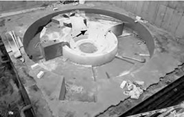
The wall thickness of the airway is 20 mm, with a geometric tolerance of ± 2 mm. Taking into account the thickness of the coating and the thickness of the heat treated oxide layer, the wall thickness is designed to be 23 mm, that is, the gas The thickness of the road wall should be uniformly increased by 1.5 mm on both sides. The machining allowance for the machining surface is designed to be 15 mm. The overall casting adopts the solid core forming process, and the solidification shrinkage rate in the circumferential direction is designed to be 1.5%~1.9%. Set equal wall thickness tie bars between the airway walls, with a height of 300 mm and a spacing of 250 mm, evenly distributed in the circumferential direction. The R angle between the tie bars and the airway wall is R25 mm. These tie bars are kept until the end of the last heat treatment, and then removed by polishing. In this way, it can play a role in preventing airway deformation in all hot working processes. During the heat treatment process, in addition to the easy deformation of the airway, other parts of the turbine casing are also prone to deformation, and the use of the material tray will play a good role in preventing deformation during the heat treatment process. Therefore, in the casting process design stage, a special heat treatment material tray is designed, which adopts a grid structure, with a grid wall thickness of 200mm and a hollow size of 200mm x 200mm with an inner rounded corner of R50mm, and is poured in the same furnace as the turbine shell.
Casting riser design
The hot joints of the castings are relatively dispersed, and the casting process design adopts a combination of open and hidden risers, which respectively supplement the flange, combustion tank hole, inner and outer walls of the shell, and the riser design scheme. In order to ensure the feeding efficiency of the riser, a heating covering agent is used when pouring the steel to a distance of 50-100 mm from the upper surface of the riser. After the completion of the casting process design, the temperature field and filling process were numerically simulated using MAGMA numerical simulation software, and the liquid phase ratio and shrinkage porosity were analyzed. According to the numerical simulation results, the optimized casting process design can meet the quality requirements of the castings
In order to prevent secondary oxidation of the steel liquid, argon gas is introduced into the mold cavity before pouring. During pouring, use an argon gas protection ring to protect the molten steel around the lower water outlet of the ladle Protect. In order to prevent splashing during pouring, the initial speed of steel entering the mold cavity should be controlled below 0.5 m/s, and the rising speed of steel should be controlled between 12-14 mm/s; Due to the inertia of the molten steel during pouring, the liquid level drops at the end of pouring, resulting in defects such as insufficient filling or slag entrapment. To avoid this problem, when the molten steel rises to a distance of 200mm from the top of the riser (pre marking), a semi flow pouring method is adopted until the molten steel smoothly fills the entire riser.
Casting core design
Ensure the surface quality of castings, avoid the occurrence and cleaning of defects, and use new sand for molding. Principle of sand selection: In areas where the wall thickness of the casting is less than 50 mm, use Fuyao Wenchang silica sand with a SiO2 content exceeding 99.26%. In areas with a wall thickness of ≥ 50 mm, the surface and back sand process is adopted. The surface sand is made of 50 mm thick new chromite iron ore sand, and the back sand is made of silicon sand; Due to the thickness of the airway wall being 20 mm and the spacing being 65 mm, the sand intake is relatively small. The airway sand core uses new chromite iron ore sand, which plays a cooling role and ensures the filling effect and surface quality. The alkaline phenolic resin sand used has a relatively large gas generation capacity, which can easily cause invasive pores on the surface of the casting during pouring. Therefore, a hard exhaust rope with a diameter of 12 mm is buried inside the sand core, and the distance between the exhaust rope and the surface of the sand core is ≤ 50 mm; The exhaust rope inside the airway core is placed in the center to guide the gas generated during pouring to the outside of the upper box for discharge. After demolding, check the surface quality of the core, clean the sand mold flash, and spray it. Use alcohol based corundum powder coating, spray three times, with a coating thickness of 0.6-0.8mm. The inner cavity annular core is shaped using a core assembly method. Before lowering the core, the core bones of two adjacent cores that are ready for welding and fixation are chiseled open to expose the core bones. Then, the core is lowered, and the position of the core is determined using a lower core template, and the core bones are welded and fixed. After the welding area cools to room temperature, use an angle grinder to clean the welding slag, fill in new sand mixed with adhesive for repair and shaping, and wait for 24 hours to harden before brushing paint and drying.
Epilogue
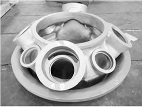
Based on the structural characteristics, composition, and quality requirements of turbine shells, the possible causes of defects in castings were analyzed, including casting process, pouring process Specific process parameters were proposed for the boxing process and heat treatment process, and Magma was used to optimize the casting process parameters. After actual production verification, the process plan is feasible.