
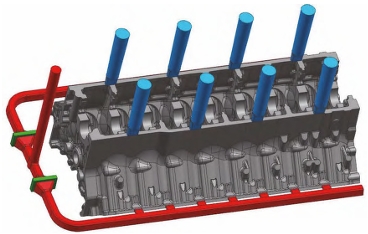
Although diesel engines have problems such as emission pollution and high noise, they are still one of the important choices for powering mobile vehicles and equipment. Diesel engines have high torque, good economic performance, and wide application. With the acceleration of industrialization in recent years, high efficiency and light weight are required for engines. Due to the high requirements for wall thickness, geometric dimensions, weight, and structure of high-end high-power diesel engines, the casting process is prone to defects such as porosity, inclusion, cold shut, shrinkage cavity, and dimensional deviation, which not only increases production costs but also causes resource waste, seriously restricting the development of the diesel engine industry.
Casting process
Considering the small minimum wall thickness of the cylinder, the smelting process uses high carbon equivalent, low alloyed raw iron liquid, and strictly controls harmful trace elements.The furnace charge ratio is 60% to 70% scrap steel and 40% to 30% recycled materials, as shown in the final chemical composition of the molten iron. The molten iron is inoculated before pouring. Good inoculation can increase the fluidity of the molten iron, increase the number of eutectic cells, reduce the tendency of white mouth, shrinkage, and residual stress. The temperature of the molten iron when it leaves the furnace is controlled at 1420℃±10℃, and the pouring temperature is controlled at 1370℃±10℃ with a flow-following inoculation. The pouring time is 25 to 30 seconds, and one package can be poured for 3 pieces, which can avoid defects such as cold shut and porosity caused by the decrease in molten iron quality and large temperature difference during pouring.
| C | Si | Mn | P | S | Cu | Cr | Ti |
| 3.15 | 1.80~1.90 | 0.70~0.80 | <0.05 | <0.1 | 0.85 | 0.25~0.28 | <0.025 |
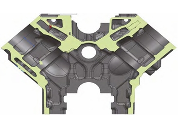
According to the structural characteristics of the cylinder block, the casting process parting surface is selected at the “V” type large section, and the exterior and internal sand cores are both made of furan resin sand.Due to the complex internal structure of the casting, multiple complex sand cores are required to form the internal cavity structure, especially the U-shaped waterway core and tappet core. To prevent sand burning and cause difficulties in cleaning in the later process, the coating is selected to be a zirconium-based high-strength anti-burning coating. Due to the large outline size of the engine cylinder block, there are significant differences in the dimensions in all three dimensions, and according to the different dimensions and wall thicknesses in three dimensions, different casting shrinkage rates of 0.91%, 0.85%, and 0.85% are adopted in the three directions of length, width, and height. The pouring system adopts a “U” type semi-closed pouring system, with the cross-sectional area ratio of each component being ΣS The ratio of ∑S horizontal to ∑S internal is 1:1.65:1.34. A filter device with a specification of 120 mm × 75 mm × 20 PPI is installed in the runner, with a total of 2 pieces, to improve the purity of the molten iron, reduce the slag inclusion defects of the casting, and slow down the flow rate of the molten iron to prevent the inflow speed from scouring the sand core inside the casting too quickly.
The sand mold assembly begins with the placement of individual internal body cores and end face cores in the internal cavity. The perpendicularity of each body core and the cylinder size are measured, and after the dimensions are correct, long bolts are used to securely lock all body cores. The sand box design uses three molds: bottom, middle, and cover. After the core assembly is completed, the middle mold is placed on the assembled sand cores, surrounded by resin sand for curing. The sand mold is then enclosed with a sealing clay strip, and the cover mold is attached to wait for casting.
trial production of castings
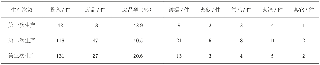
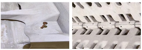
The process has been put into production in small and large batches, and the main defects are porosity, sand inclusion, and leakage. As shown in the picture, the leakage rate of the cylinder body is The leakage accounts for more than 50% of the total scrap rate, and the leaking cylinder body cannot be repaired and is scrapped. Upon inspection of the product, it was found that the leakage location was at the waterway and tappet joint of each cylinder of the cylinder body, as shown in the figure. The wall thickness at this location was only 8 mm.
Defect analysis and judgment
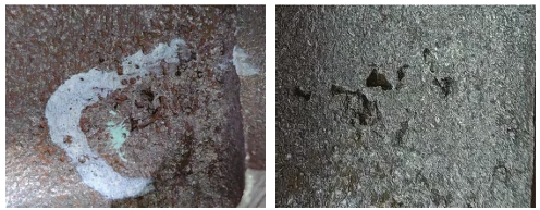
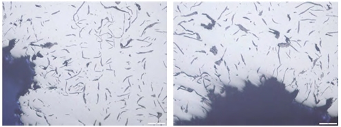
The metallographic structure was observed using a metallographic microscope. The resulting metallographic structure was far from the defect location in the matrix structure of ferrite and pearlite, and the distribution shape of graphite was composed of A-type graphite and a small amount of C-type graphite. Continuing to zoom in on the defect location, it can be seen that there are coarse and irregular blocky graphites around the defect. The graphite has certain variability. According to the metallography and defects, the fundamental reason for its formation is that the wall thickness at the defect is relatively thin, and some inclusions accelerate the cooling rate, causing the growth of graphite to be uncontrolled, resulting in lengthening and thickening of the morphology.
Numerical simulation analysis
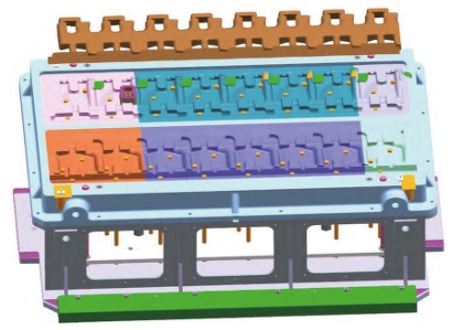
To determine the defects of the cylinder block, numerical simulation was conducted using MAGMA. The sand core, mold, pouring system, and sprue were imported into MAGMA, and material categories were defined. Cartesian grids were divided, and after parameters were determined, real-time gas evolution risk of sand mold and core in the casting, gas particle tracking of sand core gas evolution, filling temperature and gas entrainment during casting pouring were simulated and calculated for filling and solidification.
When the molten iron enters the ingate and rises with the liquid level, the U-shaped waterway core and the tappet core generate a large amount of gas and gas-generating particles when they are wrapped in molten iron. The sources of these gases are two-fold. The first is the gas generation of the sand core itself; the second is the gas generated by excessive oxidizing substances. When the molten iron enters this area, a low temperature zone appears, and from the gas generation point of view, this is also the most gas-generating point. It is analyzed that this area uses a large amount of binders and other auxiliary materials during core assembly, and when the molten iron enters this area, it rapidly decomposes the binders and other materials and oxidizes, resulting in a supercooled region with a temperature close to the solidus temperature.
After various testing methods and software determinations, it is highly likely that this defect belongs to slag inclusion and porosity defects. Coupled with the coarse structure and thin wall thickness, it leads to a high proportion of leakage defects in the casting. Through analysis, during the core assembly process, after the U-shaped waterway core, tappet core, end waterway core, and other sand cores are segmented and cored, a large amount of core bonding glue is required to fix them. However, the core bonding glue has a high gas evolution rate of 162 mL/g at 850 ℃ and a slow gas evolution rate. When the molten iron is in the solid phase region or below the solid phase temperature, the gas cannot be discharged in time to produce pores. Secondly, the coating used is an alcohol-based alkaline coating. Upon inspection of this coating, it was found that its main component is mullite (aluminum bauxite) aluminosilicate mineral, which contains a large amount of Al2O3 and a small amount of Na-based substances. After heating, these substances mix with oxygen and decompose, thus forming slag pores. Finally, the cylinder requires high strength and thin wall thickness. In smelting, large proportions of scrap steel and carbonizers are used for batch smelting. These materials also contain various elements such as Al, N, Ti that affect cast iron to varying degrees. While forming pores, it also causes shrinkage defects, which affects the compactness of the casting.
Improvement measures and verification results
(1) Change the assembly method of sand cores: Through process optimization, create corresponding process equipment, and assemble the main core and end face core outside the mold to avoid
The sand inclusion defect is caused by internal assembly. Design a dedicated core assembly and lower core assembly tooling, pre-assemble the sand core outside the mold, inspect and measure its dimensions, lock and secure it with bolts, blow out the loose sand, and lower it into the mold cavity with the lower core assembly tooling.
(2) Use hybrid coatings or graphite-based coatings instead of alkaline coatings to reduce the production of pores and slag pores. The existing coatings are alkaline coatings, which
The main component of the coating is mullite, which contains a large amount of Al, Na, and other components. Through performance tests such as anti-scorching of the coating, it was decided to use the alcohol-based 7804 coating to brush or flow coat it. The base aggregate of the coating is phosphorus sheet graphite, which effectively prevents problems such as pores, oxides, and scalding. The operation process is to brush it twice. The first pass controls its Baume value to 45 Be°. After leaving it unlit for 10 minutes, adjust the Baume value to 60-65 Be° and use natural gas to quickly bake it to dry state.
(3) For sand cores such as U-shaped waterway cores and tappet cores, cold box segmented coremaking is used instead of the original manual furan resin sand process.
While improving the strength of the sand core, it also reduces the occurrence of defects such as sand holes. The U-shaped waterway core and tappet core are designed as cold box cores, as shown in Figure 9. The basic length is based on a certain type of 8-cylinder block, and the length of the sand core is increased according to different models. After changing to a cold box, the size and strength of the sand core are improved.
(4) Instead of using a large amount of adhesive to bond the cores in the original mold cavity, iron nails are used, effectively avoiding the occurrence of air holes due to long-term gas evolution from the adhesive core glue.The original process of forming sand cores such as waterway cores and tappet cores requires the use of a large amount of core bonding glue to bond and secure the core joints. The replacement of self-tapping screws effectively avoids the air bubble defects caused by prolonged gas evolution from the core bonding glue.
(5) Adjust the melting process ratio, add high-temperature graphitization carbonizers, inoculants, etc. to obtain a dense castings, and adopt high-temperature purification of the molten iron before discharge to improve the purity of the castings. Due to the original process using a large proportion of scrap steel and recycled materials for melting, the use of carbonizers also increases with the increase of scrap steel, resulting in a significant increase in nitrogen content, which promotes the formation of carbides and affects the growth of graphite, resulting in pearlite formation, shortening and bending of graphite order, and further passivation of the end of the whole flake graphite. To improve this problem, the original process plan was optimized. In order to avoid the genetic influence of the original recycled materials on the molten iron, a 10% to 15% pig iron and 90% to 85% scrap steel blending method was adopted, eliminating the use of recycled materials, and finally adjusting the composition of the molten iron.
| 成分 | C | Si | Mn | P | S | Mo | Cu | Ti | Ai |
| 原铁液 | 3.25 | 1.48 | 0.53 | 0.022 | 0.095 | 0.024 | 0.68 | 0.0093 | 0.010 |
| 终铁液 | 3.30 | 1.88 | 0.74 | 0.023 | 0.093 | 0.28 | 0.67 | 0.011 | 0.008 |
Conclusion
After optimizing the process and taking measures, the leakage rate of a high-power engine cylinder block was reduced to less than 2%, which eliminated sand inclusion, slag inclusion,
Defects such as porosity have been significantly reduced, and the overall scrap rate has been controlled at 4% to 6%, basically meeting the quality improvement target requirements. In summary, the improvement experience can be summarized as follows:
(1) During process design, it is necessary to fully analyze and consider the deformation, fracture, and operability of sand cores, and to maximize the use of factory resources by using cold box equipment to form cores without increasing sand core strength and reducing sand inclusion defects.
(2) Elements such as Al and Na in the coating will increase the gas evolution of the sand core, which will react with oxygen to form oxide inclusions, resulting in local defects in the casting.The generation of slag pores.
(3) In terms of core assembly, the gas evolution of the binder has a large impact on the flow of molten iron, even causing the formation of oxidized slag inclusions in the casting. Through improved Fixing the sand core with self-tapping screws to reduce the amount of gas generated inside the mold.
(4) Designing a dedicated core-setting tooling and using external assembly to set the core can effectively reduce the risk of sand inclusion in the casting.
(5) When producing high-strength castings, avoid large proportions of scrap steel ingredients, add 10% to 15% of pig iron to reduce the production of nitrogen content in the molten iron, and cooperate with Use high-temperature graphitized carburizing agents and inoculants to obtain more dense castings, and adopt a high-temperature static method for iron liquid to improve its purity.