
Turbocharger turbine is a high-speed rotating component with complex curved surface structure. In order to improve the efficiency of supercharging, not only the blade profile accuracy is required, but also the reliability is required. For large-sized high-temperature alloy turbine castings, there are generally problems of poor manufacturing accuracy and unstable performance, especially for turbine castings with overall diameter greater than 300mm. Due to the long solidification time of the hub part, there are also problems of performance degradation caused by coarse grain size. By carrying out simulation optimization of turbine casting process, combined with rotating fine grain technology, it is possible to obtain turbine castings without defects such as shrinkage cavity, porosity, inclusion, air hole and crack, as well as dimensions and performance that meet requirements.
Structural characteristics of turbine castings
The outline dimension of the large-sized turbine is approximately 400mm×240mm, consisting of a trapezoidal thick part with a dimension of approximately 220mm/120mm×202mm It consists of a solid hub and 12 free-form blades with a length of 118mm wrapped around the hub surface. The blades are distributed radially and are long and thin.
The main difficulties are as follows:
(1) The turbine material is high-temperature alloy K418B, which is a nickel-based precipitation-hardened equiaxed crystal cast high-temperature alloy. The alloy contains a large amount of
Oxidation elements such as Cr, Al, Ti, which are subjected to high centrifugal force and vibration load during operation, as well as exhaust gas temperatures up to 750°C, have a significant impact on the strength, impact resistance, and durability of the material.
The impact, fatigue, and durability properties have high requirements, and the castings cannot have defects such as porosity, cracks, shrinkage, and shrinkage porosity.
(2) Compared with previous turbines, this turbine has a larger size, and the dimensional stability requirements for the blades are higher. The surface profile and the previous small-sized turbines
The wheel diameter tolerance is required to be 0.8mm. The dimensional tolerance corresponds to the requirements of CT6 in GB/T6414 Casting Dimensional Tolerance.
(3) The blade thickness at the thinnest point of the casting is only 1.8mm, which is located at the largest outer circle, making it difficult to form, and the center hub part has the largest heat node.
The diameter of the circle is 162mm, which is prone to coarse grain, resulting in substandard performance.
Analysis of turbine casting process
Based on the material requirements and purity requirements for high-temperature alloys, the vacuum induction furnace is used to melt the master alloy bar, and then the vacuum remelting method is used to pour the parts, which can reduce the oxidation, porosity, and inclusions of the alloy elements, improve the purity of the alloy, and ensure the performance of the castings. Analyzing the structure of the castings, it is found that there is only one geometric hot spot in the casting, with a diameter of approximately 162mm, located at the center of the trapezoidal hub. This area is thick and accounts for about 70% of the turbine weight, requiring a large amount of shrinkage and necessitating the installation of a shrinkage feeder. According to literature, turbine castings generally use a central feeder top pouring scheme. After analyzing the structure and dimensions of the castings, the feeder can be placed at either the friction welding end or non-friction welding end of the casting. As shown in the figure, usually, in order to ensure the welding quality of the turbine and turbine shaft, the end surface used for friction welding is placed on the bottom surface.

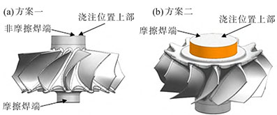
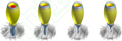
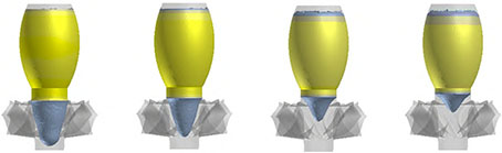
The simulation optimization of scheme 1 was conducted using ProCAST software, and it was observed that there was an isolated hot spot in the core of the turbine casting, which formed a shrinkage defect. In scheme 2, which uses friction welding with the end face facing upward, due to the small size of the friction welding end face, the required riser neck size is not met. When setting up a riser at this location, it is necessary to artificially increase the outer diameter of this location to achieve the size of the riser neck (this location is a machining location), ultimately ensuring that the casting solidifies in sequence to ensure shrinkage compensation. The solidification simulation optimization of scheme 2 was conducted using ProCAST software, and it was clearly observed that during solidification, the casting solidified before the riser neck, and the riser neck solidified before the riser, which can achieve good sequential solidification and ensure that there is no shrinkage in the interior of the casting.
Holes and porosity defects. To ensure the dimensional accuracy of the casting, the selection of the comprehensive shrinkage rate is important. For investment casting, the shrinkage factors affecting the dimensions of the casting include alloy shrinkage, mold material shrinkage, and shell expansion. Due to the large difference in wall thickness of turbine castings, combined with previous production experience data of similar parts, the comprehensive scale of this turbine is selected as follows: axial scale 3.0%, radial scale 2.7%, and during mold making, a cold wax block with a size 5-7mm smaller than the turbine center hub on one side should be prefabricated in advance and fixed in the mold to ensure the dimensional accuracy of the wax mold.
Based on the preliminary determination of the process plan, the refining design of the pouring and risers was carried out, and the size and spindle of the riser neck in plan 2 were determined.The specific dimensions of the shaped risers. It is determined that the silicon sol shell mold casting method is used for the casting of turbine castings, and the pouring method is selected as top pouring of risers, one type per piece. Usually, the common mold casting method will cause overheating at the root of the casting riser, resulting in coarse grain structure at this location, leading to poor body strength.The strength of the body may be low due to friction welding with the connecting shaft after processing the root of the riser in the process plan determined this time.Due to the strength of the weld, a fracture occurred on the turbine body during the tensile test after welding. If a riser is placed on the end face of this end, it is necessary to To solve the problem of coarse grain at the root of the riser by using the method of fine grain casting, there are strict requirements for the grain size of the casting in the technical requirements.
Please refine the grain during production. Because the large-sized turbine castings hub and risers are thick and require a long solidification time, using the usual fine grain process is not feasible.
The chemical agent has a decline phenomenon, which makes it difficult to achieve the grain refinement effect in the core of the turbine. In order to ensure the grain size of the turbine hub core, the grain refinement process of positive and negative centrifugal stirring is used to refine the grain in the core of the turbine, achieving grain refinement in the thick and large parts of the hub. According to the literature review [3], combined with experimental verification, the positive and negative centrifugal stirring process is adopted with a stirring speed of 150r/min, a positive and negative stirring time of 40s, a positive and negative conversion time of less than 5s, and the entire stirring time is determined based on simulation results.
Simulation analysis of turbine casting process
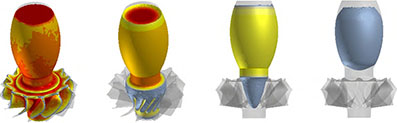
The final process plan was simulated and analyzed using ProCAST software for mold filling and solidification coupling. To ensure the filling of the blade, according to the liquidus temperature (1344.7℃) and solidus temperature (1235.7℃) of K418B alloy, the filling temperature was set to 1410℃, the flow resistance section was set to 40mm, and the total filling time was 13s. Through analysis, it can be seen that when the filling time is 4s (filling 30%), the blade part is fully filled, and then it is filled with the riser part. During the filling process, the pouring is stable, without splashing, gas entrainment, insufficient pouring, etc. When the filling is nearly complete, the blade tip begins to solidify, indicating that the set pouring temperature is appropriate and the turbine casting can ensure complete filling.
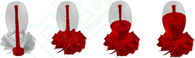
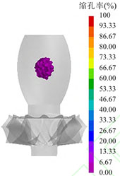
According to the solidification analysis, the blade tip of the turbine has a thin wall thickness, and the pouring has begun to solidify. The complete solidification time of the turbine blade part is 580s, the complete solidification time of the turbine casting body is 2965s, and the complete solidification time of the casting risers is 5865s. During the solidification process, the temperature distribution is uneven, with large temperature differences. The surface temperature is low, while the core and thick parts are higher, and the temperature of the risers is the highest. The temperature gradient increases from the blade tip to the blade root to the hub direction in the radial direction, and increases from the bottom to the riser direction in the axial direction. The solidification sequence is from the blade tip to the blade root in the radial direction, and from the blade root to the hub in the axial direction. The final solidification occurs at the center of the riser. During the solidification process, there is no isolated liquid phase area, which fully realizes the sequential solidification of the casting and ensures that there are no shrinkage defects such as shrinkage cavities and porosity in the casting. The analysis results of shrinkage cavities and porosity show that they are not present.
Production verification
After completing the mold making and pouring system design, trial production is started according to the conventional investment casting process, including mold making, shell making, shell baking, melting and pouring, cleaning and other processes. It should be noted that centrifugal rotation casting can be started as soon as the pouring begins (the rotation speed can be controlled at 100r/min Right), pour into the 1/3 of the riser, stop rotating to achieve the centrifugal filling of the blade; after pouring, let it stand for 3 minutes, after the blade is initially solidified, start rotating the mold in both directions according to the set parameters, agitating the metal liquid for a total agitation time of not less than 45 minutes.
Two turbine blanks were produced in two furnaces using the casting process described above, and the quality of the castings was stable. NDT, surface, and dimensional testing were performed on the turbine castings for composition and performance, with the results as follows:
(1) Chemical composition and mechanical properties: All elements are within the required range; sample analysis is conducted on the connection between the riser and the turbine body, with an average grain size of The particle size reaches 4mm, and the mechanical properties of the sample meet the requirements.
(2) After X-ray, ultrasonic and other nondestructive testing, the turbine blades and internal parts are free of defects such as porosity, inclusions, shrinkage and shrinkage porosity; the surface is penetrated Check for any defects such as cracks and inclusions that exceed the standard.
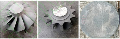
(3) Dimension detection uses a digital 3D scanning detector to obtain digital point cloud data of the turbine and blades, which is then compared with the required 3D model of the turbine casting blank. At the same time, key dimensions such as the thickness and surface profile of the blade tip position are measured and compared. The results show that the dimensional accuracy of the turbine and blades meets the requirements.The size of the turbine obtained through casting meets the requirements, as shown in the prototype turbine.
Conclusion of the study
(1) ProCAST software was used to optimize the process design of large-size turbine castings, resulting in the production of qualified large-size turbine castings.
(2) For large-sized turbine castings, a friction welding process design with the end face facing upward can be used, but relevant fine grain casting process measures are required.
(3) To ensure the dimensional accuracy of the casting, different scales in the axial and radial directions are required for the comprehensive shrinkage rate of the casting.