
In the field of heavy-duty industrial equipment, the sand suction pump plays a critical role in applications such as river dredging, silt removal, and land reclamation. These pumps are subjected to harsh environments, handling abrasive media with solid concentrations exceeding 40%. Consequently, the pump body, typically made from spheroidal graphite iron (also known as ductile iron), must exhibit exceptional mechanical properties and integrity, free from defects like shrinkage cavities and porosity. This article details our comprehensive exploration into the casting process design for a large spheroidal graphite iron pump body, focusing on overcoming the inherent challenges associated with thick-section, high-quality castings. We will delve into the intricacies of pattern making, gating system design, chilling techniques, molding control, and the vital spheroidizing and inoculation treatments, all aimed at producing a sound casting.
The pump body under consideration is a massive component, with a weight of 46,600 kg and overall dimensions of 5800 mm × 3480 mm × 2200 mm. Its wall thickness varies significantly, with a nominal thickness of 75 mm and localized sections reaching up to 355 mm. The material specification is QT500-7, a grade of spheroidal graphite iron requiring a minimum tensile strength of 500 MPa and 7% elongation. A key quality requirement is the absence of shrinkage defects in a series of threaded holes on the top surface, which are used for mating with the pump cover. The irregular geometry and stringent quality demands make this casting a formidable challenge.
Our initial assessment led to the adoption of the lost-foam casting process, utilizing an expanded polystyrene (EPS) pattern, combined with furan resin sand for mold making. This approach, often referred to as the full-mold process, offers advantages for complex shapes by eliminating the need for draft angles and complex core assemblies. However, it introduces its own set of challenges, such as ensuring adequate pattern coating and managing sand compaction to prevent mold wall collapse and sand inclusion defects.
Pattern and Mold Design Strategy
The EPS pattern was manufactured to replicate the final casting geometry, with allowances added only for machining and solidification shrinkage. The pattern was segmented into multiple blocks for efficient CNC machining and hot-wire cutting from foam boards. These blocks were then meticulously assembled and adhesively bonded to achieve high dimensional accuracy. To create a refractory barrier and improve the surface finish of the casting, the assembled pattern was coated with two layers of graphite-based paint, each applied by brushing to a thickness of approximately 0.2 mm. This coating is crucial for preventing sand erosion during metal pouring.
The mold was constructed using furan resin sand with a resin binder addition of 1.2%. A key decision was to use a multi-part flask system, essentially dividing the mold into four sections. This facilitated easier handling and, more importantly, allowed for visual inspection of core alignment during mold assembly. The core assembly consisted of six resin sand cores, reinforced with internal chills and chaplets where necessary. The largest core was a specially designed monolithic piece. Core reinforcements included both welded steel arbors for smaller cores and a cast iron core grid for the massive central core. All cores were coated with zircon-based facing sand to enhance refractoriness and surface quality.
Gating and Feeding System Engineering
The design of the gating and feeding system is paramount for a sound casting. Given the size and weight of this spheroidal graphite iron component, we implemented a two-tier bottom-gating system with step gates. The lower gate system was primarily responsible for the initial mold filling, while the upper gate, located 1740 mm above the bottom of the casting, served to reduce turbulence and slag entrapment during the latter stages of filling.
The hydraulic head for metal flow was calculated using the following fundamental equation:
$$H_p = H_{flask} + H_{pouring\_cup} – \frac{C}{2}$$
where \(H_p\) is the effective metallostatic pressure head, \(H_{flask}\) is the height of the flask, \(H_{pouring\_cup}\) is the height of the pouring cup, and \(C\) is the height of the casting.
The pouring time was estimated based on the total poured weight \(G_L\):
$$t = k \sqrt{G_L}$$
where \(k\) is an empirical constant dependent on casting geometry and wall thickness. For this thick-section casting, a rapid pour was desired to minimize temperature gradients, leading to a calculated pouring time.
The choke area of the gating system \(A_{choke}\) was determined to control the flow rate:
$$A_{choke} = \frac{G_L}{\rho \cdot \mu \cdot t \cdot \sqrt{2gH_p}}$$
where \(\rho\) is the density of molten spheroidal graphite iron (approximately 7300 kg/m³), \(\mu\) is the discharge coefficient (taken as 0.4 for resin sand molds), and \(g\) is the acceleration due to gravity (9.8 m/s²). The gating system areas were then proportioned as follows: \(A_{sprue} = A_{choke} / 0.8\), \(A_{runner} = 1.2 \times A_{sprue}\), and \(A_{ingate} = 0.8 \times A_{sprue}\). The final dimensions were adjusted to match available standard sizes.
To address the pronounced shrinkage tendency of spheroidal graphite iron, a robust feeding system was designed. Six Ø180 mm insulated exothermic feeder heads were strategically placed on the top surfaces near the bearing housing areas. These feeders utilize exothermic compounds to maintain a longer liquid state, enhancing their feeding efficiency. Additionally, two Ø140 mm conventional open feeders were placed on non-critical mounting pads to aid in feeding, slag trapping, and venting. Multiple vent channels were installed at the highest points of the mold cavity to ensure the escape of air and gases generated during the pour.
Application of Chills for Controlled Solidification
Controlling the solidification of thick sections in spheroidal graphite iron is critical to prevent shrinkage porosity, graphite flotation, and degeneration of graphite morphology. Prolonged solidification times can lead to reduced nodule count and spheroidization efficiency. We employed a combination of external and internal chills to accelerate cooling in critical areas.
For sections with a modulus (volume-to-surface-area ratio) less than 9 cm, standard cast iron external chills were used. The most critical area was the top flange containing the threaded holes. A continuous ring of external chills was placed around this region to promote directional solidification towards the feeders. Similarly, external chills were applied to the bearing seat areas.
For the massive section exceeding 300 mm in thickness, where external chilling is insufficient, formed internal chills were inserted. These chills, made from a material compatible with the base iron, become an integral part of the casting. Their purpose is to significantly reduce the local solidification time, ideally keeping it below 50 minutes to ensure a high nodularity (above 80%). The strategic placement of chills was crucial for establishing a favorable temperature gradient.
The following table summarizes the chill application strategy:
| Location | Chill Type | Purpose | Target Modulus Reduction |
|---|---|---|---|
| Top Flange (Threaded Holes) | External Cast Iron Ring | Prevent shrinkage in machined areas | By ~40% |
| Bearing Housing | External Cast Iron Plates | Ensure soundness for load-bearing | By ~35% |
| Central Thick Section (>300mm) | Formed Internal Chills | Avoid gross shrinkage and graphite degradation | Solidification time < 50 min |
Spheroidizing and Inoculation Treatment Protocol
The heart of producing high-quality spheroidal graphite iron lies in the treatment process. We implemented a multi-stage treatment to ensure consistent nodularity and a fine matrix structure. A pre-conditioning step was employed to enhance the nucleation potential of the base iron. Before tapping, 0.4% of a proprietary preconditioning agent was added to the furnace. This step is vital for large castings to improve fluidity and reduce shrinkage tendency.
The spheroidizing treatment was performed using a sandwich method in a treatment ladle. We used a heavy rare-earth containing spheroidizer, type DY-7F, at an addition rate of 1.05% of the tapped iron weight. This was covered with a proprietary inoculant, CALBALLOY, added at 0.4%. The use of rare-earth aids in counteracting the deleterious effects of trace elements like lead and antimony, which is crucial for heavy sections.
To combat fade and ensure a high nodule count throughout the massive casting, we employed a multi-stage inoculation process. The primary inoculation occurred during the tap via the sandwich method. A final, post-inoculation was carried out during pouring using a flow-through inoculator, adding 0.15% of a highly efficient inoculant, YFY-1A. This late inoculation significantly enhances graphite nucleation in the last metal to solidify.
The effectiveness of the treatment can be monitored through the residual magnesium content. We aimed for a residual magnesium level between 0.035% and 0.055%. The chemical composition control is summarized below:
| Element | Pre-Treatment Target (%) | Post-Treatment Target (%) |
|---|---|---|
| Carbon (C) | 3.4 – 3.5 | 3.2 – 3.4 |
| Silicon (Si) | 1.5 – 1.6 | 2.3 – 2.5 |
| Manganese (Mn) | 0.35 – 0.45 | 0.35 – 0.45 |
| Phosphorus (P) | ≤ 0.04 | ≤ 0.04 |
| Sulfur (S) | ≤ 0.03 | ≤ 0.02 |
| Copper (Cu) | – | 0.65 – 0.75 |
| Magnesium (Mg)res | – | 0.035 – 0.055 |
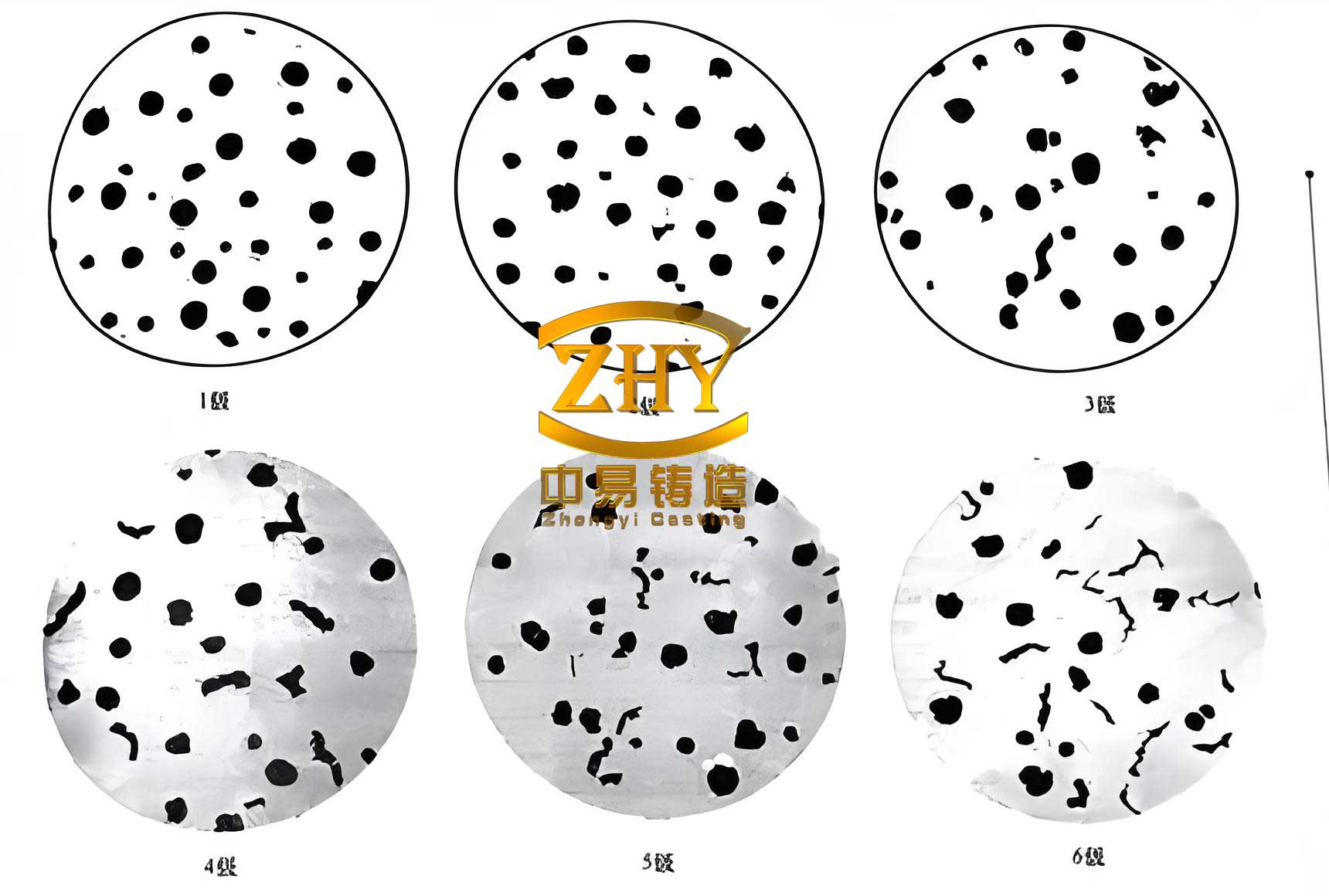
The image above illustrates the typical microstructure we aim for in spheroidal graphite iron, showing well-formed graphite spheroids embedded in a matrix of ferrite and pearlite, which is essential for achieving the required ductility and strength in the pump body.
Melting, Pouring, and Solidification Control
The melting was conducted in a medium-frequency induction furnace, ensuring precise temperature and composition control. The pouring of this massive spheroidal graphite iron casting required coordination. It was executed using a three-ladle sequential pour to maintain a continuous, high flow rate. The pouring temperature was carefully selected between 1330°C and 1350°C. A high temperature helps maintain fluidity for complete mold filling, but it must be balanced against increased shrinkage and gas absorption risks.
During pouring, the gating system was designed to maintain a non-turbulent fill. The molds were secured with four 10-tonne weights placed on top of the cope, supported by steel pipes to distribute the load and counteract metallostatic pressure. After pouring, the inherent insulating properties of the furan resin sand were leveraged to promote slow and uniform cooling. This in-mold cooling acts as a stress-relieving anneal. Based on our experience with heavy-section spheroidal graphite iron castings, the mold was left intact for 240 hours (10 days) before shakeout. The weights were loosened two days prior to shakeout to relieve any residual stress gradually. The shakeout temperature was strictly controlled to be below 300°C to prevent thermal shock and the formation of excessive surface scale.
Results: Mechanical Properties and Microstructural Analysis
Upon shakeout and removal of the feeder heads and gating system, the pump body casting was inspected. Visual and non-destructive testing confirmed the absence of major defects like shrinkage cavities or cold shuts in critical areas. To quantitatively assess the quality, separately cast test coupons (attached to the casting) were used for mechanical and metallographic testing.
The tensile properties and hardness consistently met and exceeded the QT500-7 specification. The microstructural analysis revealed a high degree of nodularity and a controlled matrix. The following table presents the data from three different test lugs attached to the casting:
| Sample No. | Tensile Strength (MPa) | Yield Strength (MPa) | Elongation (%) | Hardness (HB) | Graphite Nodule Count (per mm²) | Nodularity (%) | Pearlite Content (%) |
|---|---|---|---|---|---|---|---|
| 1 | 460 | 325 | 11.0 | 175 | 120 | 92.1 | 54.9 |
| 2 | 490 | 330 | 7.0 | 177 | 135 | 92.0 | 60.7 |
| 3 | 485 | 330 | 7.5 | 179 | 110 | 90.5 | 57.9 |
The average graphite nodule diameter was in the range of 4.5 to 5.2 μm, indicating effective inoculation. The nodularity, a measure of the percentage of graphite present as spheroids, was consistently above 90%, which is excellent for a casting of this section size. The matrix structure was a mixture of ferrite and pearlite, with the pearlite content between 55% and 61%, contributing to the strength. These results confirm that the spheroidal graphite iron produced had a fully spheroidal graphite structure with the desired mechanical characteristics.
The relationship between nodularity and mechanical properties, especially elongation, can be expressed empirically. A higher nodularity generally correlates with better ductility. While the exact relationship is complex, a simplified view for this iron grade suggests that maintaining nodularity above 80% is critical for achieving the specified 7% elongation. Our process achieved over 90%, explaining the superior elongation values obtained.
Discussion on Process Efficacy and Challenges
The successful production of this pump body validates our integrated process approach. The lost-foam process, while challenging in terms of pattern coating integrity and sand compaction, proved effective for this complex geometry. The key was the meticulous coating application and the use of high-strength furan resin sand to resist erosion.
The gating and feeding system design, backed by hydraulic calculations, successfully managed the flow of over 46 tonnes of molten spheroidal graphite iron, minimizing turbulence and ensuring adequate feeding. The effectiveness of the chill design is evident from the soundness of the thick sections and the threaded hole areas. The solidification sequence, directed by the chills and feeders, prevented the formation of mid-section shrinkage.
The multi-stage spheroidizing and inoculation treatment was undoubtedly the cornerstone of success. The pre-conditioning, combined with rare-earth spheroidization and late-stream inoculation, effectively countered fading and ensured a high, uniform nodule count throughout the massive casting volume. The chemical composition control, particularly the low sulfur level post-treatment and the balanced silicon content, was instrumental in achieving the desired microstructure and avoiding defects like chunky graphite.
One of the significant challenges with such heavy spheroidal graphite iron castings is the calculation of solidification time and feeding demand. The Chvorinov’s rule provides a basic framework:
$$t_s = k \left( \frac{V}{A} \right)^n$$
where \(t_s\) is the solidification time, \(V\) is the volume of the casting section, \(A\) is its surface area, \(k\) is a constant dependent on mold material and metal properties, and \(n\) is an exponent typically close to 2. For spheroidal graphite iron, the solidification mode (mushy) complicates this, and practical experience combined with simulation software is often used for refinement. Our use of internal chills was a direct response to the long calculated solidification times for the thickest sections, ensuring they fell within the safe window for maintaining graphite spheroidization.
The economic and technical feasibility of producing such large spheroidal graphite iron components hinges on precise process control. Any deviation in treatment efficiency, pouring temperature, or mold stability can lead to catastrophic defects. Our process demonstrated that with careful planning and execution, these challenges can be overcome.
Conclusion
This detailed exploration into the casting process for a large sand suction pump body made from spheroidal graphite iron has demonstrated a viable and robust methodology. By integrating lost-foam pattern technology with a rigorously designed resin sand molding process, a sophisticated gating and feeding system, strategic use of chills, and a meticulously controlled multi-stage spheroidizing and inoculation treatment, we have successfully produced a high-integrity casting. The mechanical properties and microstructural analysis confirm that the casting meets the demanding QT500-7 specification, with excellent nodularity and freedom from shrinkage defects. This work provides a comprehensive reference and a set of validated technical guidelines for the foundry industry engaged in the production of similar heavy-section, high-performance spheroidal graphite iron castings, such as pump bodies, valve housings, and other critical industrial components. The repeatability of this process ensures that quality can be consistently achieved, paving the way for more reliable and durable equipment in demanding applications.