
1 Process plan
The sand mold material is resin sand, and the casting method is gravity casting.The interface with the mold is set to CONIC, with a heat transfer coefficient of 600 W/(m2·k), moldThe heat exchange with the outside is set to air cooling [6]. The planetary system was drawn using UG softwareThe 3D model of the frame is shown in Figure 1.
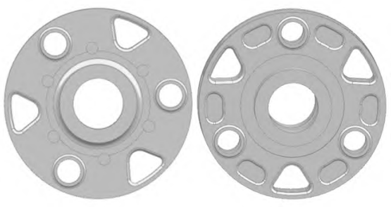
Figure 1 Three-dimensional model of planet carrier
Built a 3D model of the casting system using UG software and saved the model as aIn xt format, the model was meshed after importing the VM module of ProCASTDivided [7]To ensure accurate calculation results and improve calculation efficiency, castings and molds areThe grid division was implemented using tetrahedral elements with different side lengths (face grid 116250, volumeGrid 3026259), as shown in Figure 2.
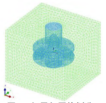
Figure 2 Grid division of planet carrier
The gate shape is designed as a tapered shape with a large upper part and a small lower part (1:25 or 1:50), which facilitatesPositive pressure flow at the gate to prevent air suction or entrainmentFor the structure of the gate cup,There are mainly funnel-shaped pouring cups and basin-shaped pouring cups.Among them, the basin-shaped pouring cup isThe production process is complex and the metal consumption is large.Therefore, in order to reduce metal consumption and metalFor the entrainment oxidation of liquid, this article selects a funnel-shaped pouring cup.The design of the runner is in the pouringIt is particularly important in the system, and the factors to be considered in the design include: the position and internalThe structure of the runner.The selection of the runner location should meet the solidification sequence or shrinkage requirements.In order to prevent the gas from accompanying and flushing sand during the liquid inflow process, the sprue is designedThe inlet connection uses rounded corners.The internal runner is a section of the pouring channel where the metal liquid enters the mold cavity.The internal sprue is designed as a narrow and deep trapezoid structure for easy skimming。
According to the design concept, two pouring systems, top pouring and bottom pouring, are drawn, as shown inAs shown in Figure 3, by analyzing the casting process of the planet carrier, a more suitable casting method was selected.Pouring system.
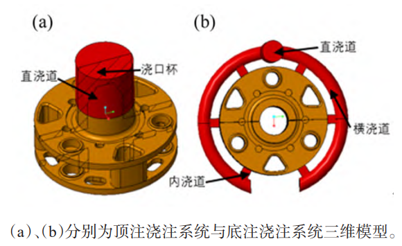
Figure 3 Planet carrier pouring system
2 Process simulation and optimization
According to the actual working conditions, the pouring temperature and preheating temperature during mold filling simulation are1300℃ and 300℃ are selected.Figure 4 shows the filling mold of the top pouring systemProposed process.
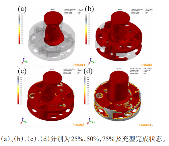
Figure 4 Molding process of top pouring system
When the top pouring system is filled with 25%, the metal liquid has filled the neutral column, showingThe situation of inflow into the upper annular plate.As the filling continues (50% filling), the upper annularThe filling of the plate and support plate is basically completed, and some of the molten metal has flowed into the lower annular plate.WhenWhen the mold filling reaches 75%, the ring plate and support plate of the planet carrier have been fully filled.The overall filling of the 18.48 s casting is complete, and the molten metal has filled the entire cavity.From Figure 4The filling results of the mold can be found that although there is some fluctuation in the liquid surface of the metal, the wholeThere was no splashing or obvious under-filling during the filling process.The top-gating systemThe uniform filling structure is simple, easy to fill, with less consumption of metal liquid and temperature distribution of metal liquidThe filling simulation process of the bottom pouring system is shown in Figure 5.
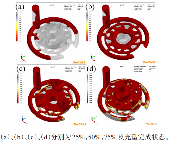
Figure 5 Molding process of the bottom pouring system
In order to determine the solidification sequence, the top pouring system and the bottom pouring system are compared.The casting solidification simulation was performed, and the results are shown in Figure 6.From the figure, it can be found that the top injection systemThe unified bottom injection system has not been found to have any collapses or cavities after solidification.
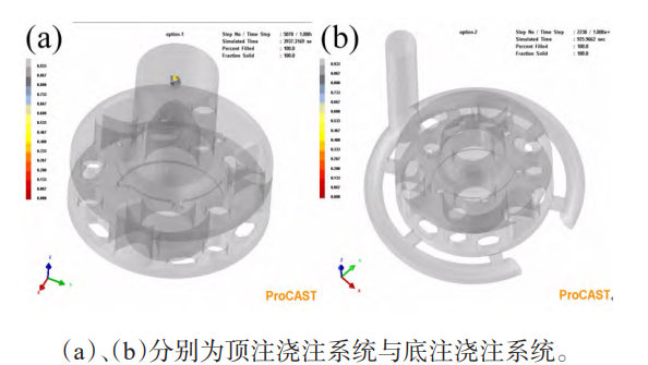
Figure 6 Solid phase distribution at full solidification
Figure 6(a) shows the solid phase distribution diagram of the top pouring system, which can be found in the casting fromThe solidification begins at the lower temperature of the distal edge.At a solid fraction of 55.6%, due to theThe support plate is in the necessary channel for the molten metal to flow into the lower annular plate, so it solidifies first.At 925 s, the solidification of the castings ended, and the solidification process of the planet carrier castings proceeded from the outside to the inside,The sequence is from bottom to top.Figure 6(b) shows the solid phase distribution of the bottom pouring system, with solidification starting from the bearing passage.The thin wall thickness of the hole edge, support plate edge, and internal runner.Compared to the top injection systemIn the bottom-stake system, the solidification of the upper and lower annular plates is not synchronous, but the lower annular plateThe plate solidifies before the upper ring plate. At the end of the solidification process, the support plateOnly the areas connected to the center column and the thick wall of the center column, as well as the runner and sprue, areand the solidification is completed.
Through the Niyama criterion in ProCAST [13], confirming the shrinkage cavity in the casting.The simulation results are shown in Figure 7.Compare the bottom and top pouring systemsFrom the simulated defect distribution, there are fewer shrinkage defects in the top pouring system, which showsThe defects mainly concentrate on the thick wall around the center column, as shown in the red circle in Figure 7(a).Marking area.For the bottom pouring system, the upper ring plate and lower ring plate areThe solidification process is not carried out synchronously, with sprues, runners, and center columns as castings.The final solidification point of the alloy is prone to forming shrinkage defects .The top pouring system is used for filling the moldThe temperature gradient during cooling is beneficial to sequential solidification, and the upper and lower annular plates are solidified simultaneously.Due to its solid structure and self-shrinkage function, it only forms a small amount of porosity around the thick wall of the center column.The shrinkage cavity defect.Compared to the top-gating system, the bottom-gating systemThere are more overall defects, especially at the neutral column, where the defect level is more serious.Therefore,The top pouring system is more suitable for the casting of planetary frames.
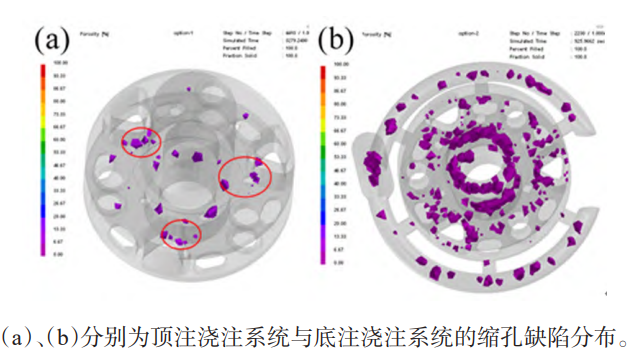
Figure 7 Distribution of shrinkage cavity defects
Chills are either external or internal, with external chills mainly used for wall thicknesses of 100Castings below 100mm.The external chills can be divided into direct external chills and indirect external chills based on the relative position of the casting.There are two types of chills: direct and indirect external chills. Direct external chills are suitable for castings that come into direct contact with the chill.situationFor ZG35CrMo quenching and tempering alloy steel castings, it is necessary to apply a layer ofRecently, direct external chill has been used to prevent the formation of shrinkage defects.It has been discussed in 2.1.2 of this article.It is understood that the hot spot exists in the middle of the lower annular plate, which is the thickest part of the wall, thusSome defects are generated.The optimized solution is shown in Figure 8, where the red part is the risk.The green part is the outer chill.In order to achieve solidification from bottom to top and from outside to insideThe sequence is as follows: a 12mm thick hole is set in the middle of the annular plate under the planet carrier, and the inner wall of the hole isThe external chills of 10mm are used to avoid excessive shrinkage defects in the casting.
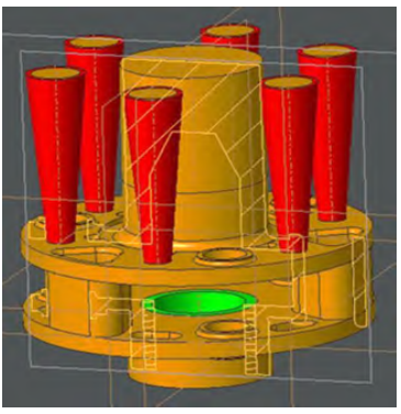
Figure 8 Riser and External Chill Design
The filling process of the planetary gear carrier after structural optimization is shown in Figure 9.The molten metal flows into the cavity from the top of the neutral column, and when the mold is filled to 25%, the molten metal has already flowedEnter the lower annular plate (Figure 9(a)).When the filling reaches 50% (Figure 9(b)), lower annular plateIt is already full, and the support plate is also in a state of being ready to be filled.When it is filled to 75% (Figure 9[c]), the annular plate and the intermediate support plate have been filled.As the molten metal liquid continues toContinuous injection, the neutral column and the riser were filled at 20.71 s, as shown in Figure 9(d).According to the filling simulation results of the optimization scheme, the liquid surface fluctuation is small, and the molten metalThe liquid does not splash, effectively avoiding defects such as air entrainment and sand washing.In addition, the planetary partsThe casting is filled from bottom to top in a sequential manner, and the filling sequence also meets the requirements of gravity shrinkage compensation, with no significant underfilling observed. The overall filling effect is good.
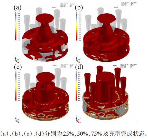
Figure 9 Molding process of the improved scheme
The distribution of entrapped gas before and after optimization of the top injection system is shown in Figure 10.Figure 10(a)To optimize the gas entrainment defect of the front top injection system, compared to the improvement plan, due to the lack ofThere is a lot of entrapped air in the design of the risers, the connection between the center column and the support plate, and the center column.Figure 10(b) shows the improved gas distribution in the improved solution.During the pouring process, the gas in the gateThe body disappears first, followed by the gradual disappearance of gas in the entire cavity, and finally the complete disappearance of gas at the riser.discharge.Because the exhaust channel is reserved when designing the pouring system, the optimizedThe solution did not have air entrainment.
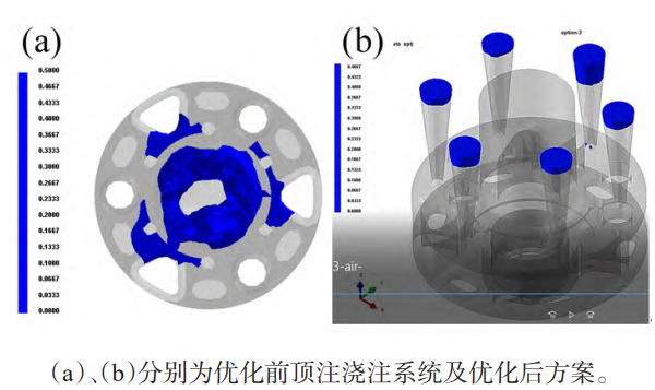
Figure 10 Comparison of gas-wrapping defect distribution before and after optimization
Figure 11 shows the distribution of shrinkage cavities in the improved design, with a large number of aggregated shrinkage cavities clustered inGate cup.There is basically no shrinkage cavity in the casting, only around the center column and support plateA very small amount of shrinkage cavity was found at the edge, which had little impact on the overall quality of the casting.The reason for the reduction in shrinkage is that the design of the external chills eliminates the adverse effects of hot spots.Compared to the distribution of shrinkage cavities before optimization in Figure 7(a), the distribution of shrinkage cavities in the optimized casting isThe shrinkage cavity in the annular plate is also greatly reduced.This is mainly because the upper annular plate isLiquid shrinkage is obtained, effectively avoiding shrinkage cavities.

Figure 11 Distribution of shrinkage cavity in optimization scheme
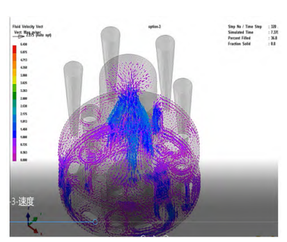
Figure 12: Distribution of velocity field in the optimization scheme
During the solidification process of castings, various stresses will be generated, mainly including thermal stress, phaseVariable stress and mechanical resistance stress.If the maximum stress is greater than the rated tensile strength of the casting,The excessive internal stress will cause cracks in the interior or surface of the casting.It is necessary to formulate corresponding improvement plans or measures to address one of the hidden dangers of product quality.In order to analyze the quality of the molded parts more comprehensively, through the simulation analysis of the stress field, the stress distribution and the deformation characteristics of the molded parts can be analyzed.Figure 1. Evaluation of the quality of planetary carrier molding parts from the perspective of equivalent stress.CastingThe stress field distribution diagram, as shown in Figure 13, indicates that the key parts of the casting are all under low stress.The force state does not show a large stress concentration, which is beneficial to good casting qualityThe planet carrier casting.
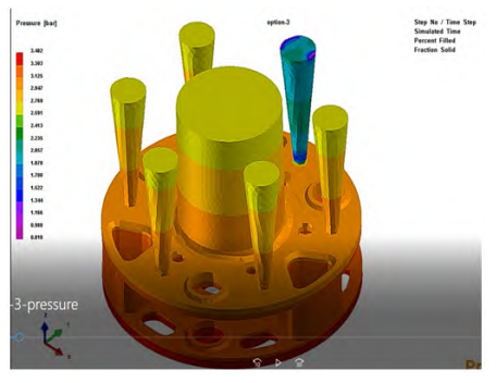
Figure 13 Distribution of Stress Field
3 Conclusion
The casting process of the planet carrier casting was conducted through the ProCAST software.Simulation and optimization have resulted in a casting process with fewer defects. The simulation results indicate that: 1)Compared to the bottom pouring system, the top pouring system is used for casting the planet carrier.The filling process is stable, achieving the orderly filling from bottom to top and the orderly solidification from outside to inside.There are fewer shrinkage defects.For top-gating systems, some of the defects are mainly concentrated in the2) The pouring temperature and preheating temperature are selected as1300℃ and 300℃ help to reduce filling under the premise of ensuring casting qualityTime.In order to further reduce the defects of the top pouring system parts, the planet carrierThe middle part of the lower annular plate, that is, the inner wall of the through hole, is designed with a direct external chilling iron, which reducesThe probability of shrinkage cavity occurrence is reduced, and 6 risers are added on the upper end of the planet carrier center to strengthen the fillingAfter process optimization, the filling speed is stable and the shrinkage defects are significantly reduced.The application of chill iron ensures smooth feeding channels, and there is basically no shrinkage or porosity in the casting.Hole defects and entrapped gas defects completely disappear, and the key parts of the casting are in low stress state.The force state is beneficial to the improvement of casting quality and yield.