
1. Process Status
Grid fin surface structure for CZ-2D and CZ-4B carrier rocketsAs shown in Figure 1, the rudder surface consists of a rudder stock, a rudder frame, blades, and an adapter plate.The rudder stock is connected to the rotating shaft of the rudder, which is the main load-bearing structure, and it is used forThe plate is screwed to the rocker arm of the deployment locking mechanism.It is made of TC4 titanium alloyThe plate is machined, then spliced into a grid structure and laser-engravedWelding;rudder mounting hole, adapter plate, and inner and outer curved surfaces of rudder surfaceAll are machined after the overall molding of the product to ensureThe linkage of other systems and the product processing process flow are shown in Figure 2.
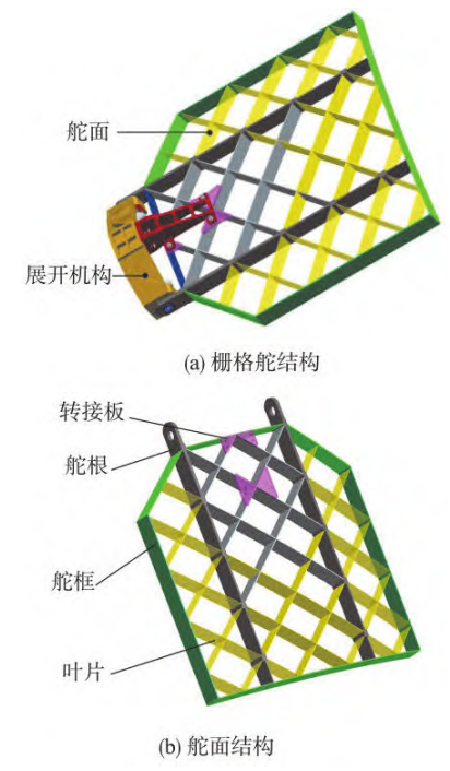
Fig.1 Grid rudder surface structure
The current process methods mainly have the following problems:1) Rely on the skill level of the operator.The rudder surface is a closed-type jointInsert form, parts are mostly thin-walled flat plate structures, which are prone to deformation after processingThe shape, the difficulty of deformation control and correction during the processing process;the assembly before weldingTo meet the requirements of welding assembly clearance, operators need to combine theReal-time shape correction of parts is carried out during assembly.
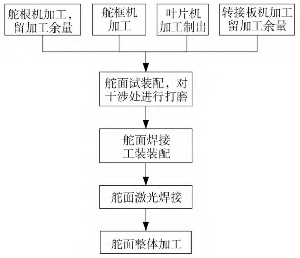
Fig.2 Rudder surface processing process flow
2) Product reliability needs to be improved.Currently, laser welding is used.The process plan of is easily affected by assembly clearance, and it is prone to incomplete welding and burning.Defects such as cracks and wear;affected by welding deformation, the position of the weld after welding is prone toCrack defects caused by sizing.After welding, it is necessary to perform overall machining and addThe work is difficult and there is deformation.Therefore, it is proposed to adopt the integral casting scheme of the rudder surface to replace the currentprocess plan to achieve the goal of improving product reliability.
2 Structural optimization design
2.1 Material selection
The rudder surface is mainly used for flight attitude control during the rocket’s return process.Mainly affected by aerodynamic forces and aerodynamic heating, therefore, in order to improve the performance of the rudder surfaceThe use performance of , both the normal temperature performance and high temperature performance are superiorZTA15 high-temperature titanium alloy is a Soviet-developedA near α-type titanium alloy, consisting of Ti-6Al-2Zr-1Mo1V, has good room and high temperature strength, good thermal stability, and good corrosion resistance.Sex and welding performance, has been widely used in the manufacture of long-term under 500 ℃ conditionsTime working on aircraft engine parts, which can be held at 500 ℃The long-term tensile strength exceeds 500 MPa, while TC4 (explained) material isThe tensile strength was measured to be 500 MPa at 350℃.
2.2 Optimization of rudder structure
The rudder structure was optimized on the basis of the original welding structure1) The use of a locally swept leading edge structure results in a lower zero-lift drag than a conventionalThe structure-based grid rudder reduces 30% to 40% compared to the overall swept grid rudderSignificant drag reduction effect, and can effectively improve the stability at transonic speed2) Combine the moldable characteristics of complex casting structures,Further optimize the grid layout and structural shape on the basis of the frame-type rudder surfaceThe design of the structure is improved from the original fixed wall thickness to a gradually changing wall thickness design, achieving structural reductionand also ensure sufficient strength and rigidity;3) cancel the rudder surface protectionThermal spraying requirements;4) The interface position of the original deployment mechanism was integratedSuccessfully canceled the design of the structural connection plate.Optimized the structure of the rudder surfaceAs shown in Figure 3, the rudder model is shown in Figure 4.
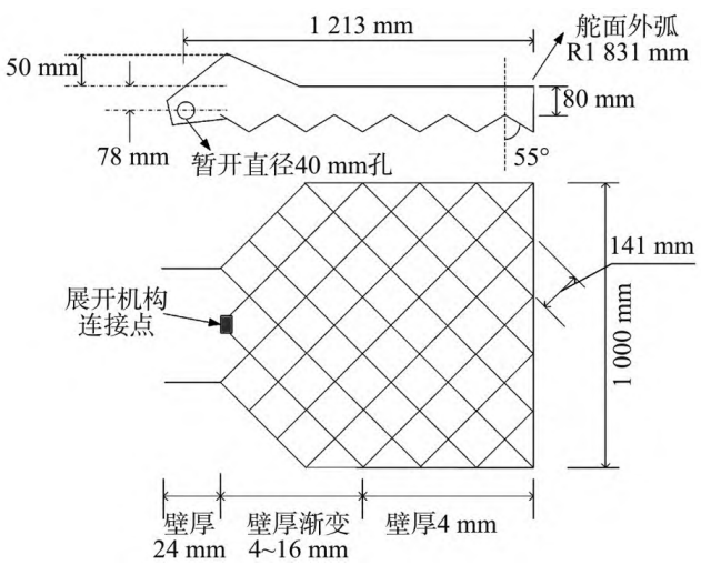
Fig.3 Schematic diagram of an optimized rudder surface
structure
Fig.4 Rudder surface casting model
3 Research on the casting technology of rudder surface
According to the requirements of the rudder model, the overall implementation plan for the preparation of the rudder casting was determined, as shown in Figure 5.
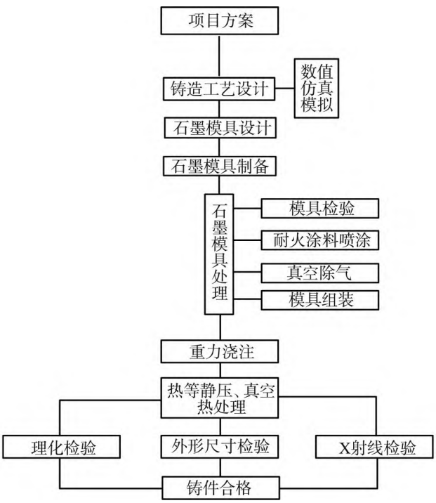
Fig.5 Overall implementation plan
3.1 Foundry process design
According to the structure of the casting, the casting process needs to be reasonably designed, including castingSet the shrinkage rate of the part, select and design the parting surface of the mold, and design the gating systemThe design and casting method are determined according to the principles of casting process design.Select an open pouring system and provide appropriate static pressure head.Comprehensively consider the structural characteristics of the rudder surface casting to design the process plan.Note: The system consists of 5 levels, including 1 main runner and 5 branch runners.One runner, 5 sprues, 15 runners, 37 internal sprues.Internal spruesPlace it at the junction with the rib plate to ensure that the rib plate can be completely filled, and to preventTo prevent deformation, add tensioning ribs between the rudder roots.Divide the product structureConsidering the structural characteristics of the rudder surface castings, the bottom pouring method is adopted.The injection system is shown in Figure 6.
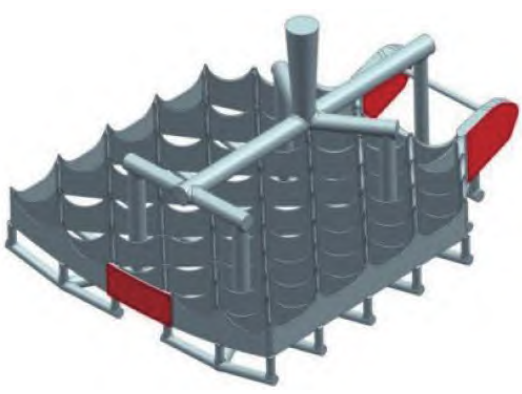
Fig.6 Bottom gating system
3.2 Numerical simulation of casting
Simulate the casting process using the process parameters of ZTA15Simulation, as shown in Figure 7.From Figure 7, it can be seen that during the mold filling process of the rudder surface casting,The alloy liquid is directly injected into the cavity at the bottom of the rudder surface through the internal runner, and the alloyAfter the liquid is filled into the cavity at the bottom of the casting, it begins to fill steadily from bottom to toptype, eliminating turbulence during the filling process and reducing the casting defects of the rudder surface.The possibility of casting defects such as porosity and slag inclusion inside the part.

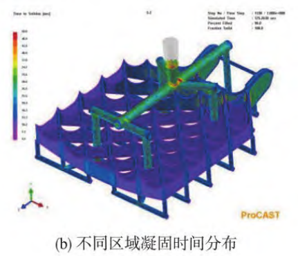
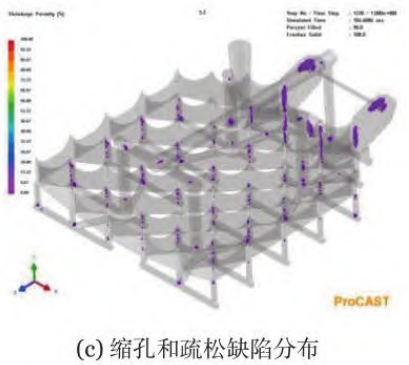
Fig.7 Casting simulation
3.3 Mold design and manufacturing
The main reasons for selecting graphite as the mold material are: 1) graphite is a heat-resistant material,Chemical stability and high refractoriness;2) high strength, and graphiteThe degree of increase in strength;3) low coefficient of thermal expansion;4) graphite on the meltingTitanium melting has good wettability.At the same time, the selection of machining methods for mold manufacturing can effectivelyEnsure the dimensional accuracy of the mold within ±0.2 mm, thereby ensuring the castingQuality.Machined graphite molds are used as molds, and design considerations are taken into accountThe shrinkage rate, coating spraying, positioning and other factors can effectively ensure the quality of the product.surface quality and size.In summary, machined graphite type is adopted asMolds should be designed considering shrinkage rate, coating, positioning, and other factors.can effectively ensure the surface quality and size of the product.After assembly,The mold is shown in Figure 8, and the machined graphite mold is shown in Figure 9.
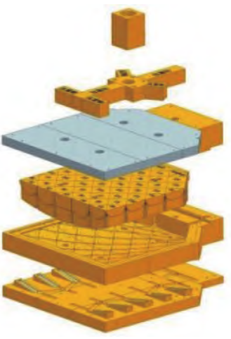
Fig.8 Graphite mould structure
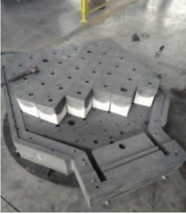
Fig.9 Machined graphite mould
To meet the requirements of high-precision casting size detection,The three-dimensional dimensional scanning was used for the part, and the detection results are shown in Figure 10.All meet the CT8 requirements of GB/T 6414.At the same time, the castingPerform X-ray nondestructive testing on designated parts (main load-bearing interface) to achievecomplies with the internal quality standard of GJB2896A-2007 Class I castings.MachiningAfter completion, the physical dimensions of the product were measured and weighed, and the measured dimensions were allMeet the requirements of the design drawing, the actual measured quality is 48.25 Kg, which meets the requirement.The requirement for the rudder surface is 50 Kg. The physical casting of the rudder surface is shown in Figure 11.The productThe physical object after painting is shown in Figure 12.
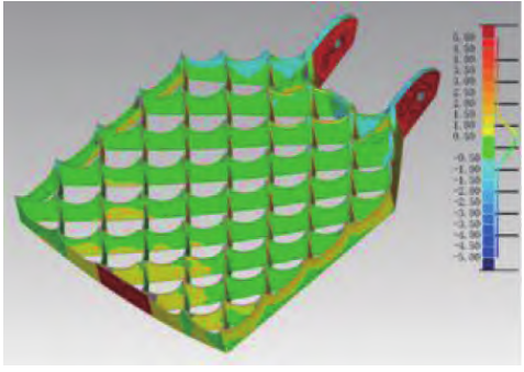
Fig.10 Graphite mould structure
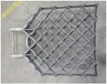
Fig.11 Machined graphite mould
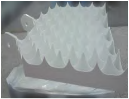
Fig.12 Actual diagram of the final state of the rudder surface
5 Conclusion
This article proposes a casting process for the machining of grid rudder surfaces.Art method, carried out the technological breakthrough of casting forming technology, implemented the process designCalculation, numerical simulation, test piece production and testing, obtaining the results that meet the technical requirements.The product required by the technical indicators, the relevant design of the reusable rocketwhich is of guiding significance for manufacturing.