
In my extensive involvement with foundry operations, particularly in the realm of green sand mold casting for gray iron components, I have consistently observed that slag inclusions and sand holes are two of the most prevalent and frequently confused defects. The green sand process, valued for its cost-effectiveness, material availability, sharp mold definition, operational convenience, elimination of drying cycles, short production lead times, and easy shakeout, nonetheless harbors inherent weaknesses. These include relatively low mold strength and the presence of moisture, which predispose castings to defects like gas porosity, slag inclusions, and sand holes. This article, drawn from my firsthand experience and technical investigations, aims to provide a detailed, comparative examination of slag inclusions and sand holes. I will elucidate their morphological signatures, outline systematic discrimination methodologies ranging from simple to advanced, and propose practical preventive measures. To enrich the discussion, I will incorporate theoretical models, quantitative analyses, and extended case studies, ensuring the key term ‘slag inclusions’ is thoroughly explored throughout.
The fundamental challenge in defect diagnosis stems from the superficial similarity between slag inclusions and sand holes—both manifest as irregular cavities on or within the cast surface. However, their origins, compositions, and implications for process control are distinctly different. A precise identification is the critical first step toward implementing effective corrective actions and enhancing yield.
1. Detailed Characteristics and Formation Mechanisms
From my analysis, understanding the genesis and appearance of each defect is paramount. I will delineate their features systematically.
1.1 Slag Inclusions: Nature and Attributes
Slag inclusions, a term I encounter constantly in quality audits, refer to foreign, non-metallic inclusions trapped within the casting matrix or on its surface. These are primarily oxides, sulfides, or silicates originating from the molten metal itself—from slag carried over from the furnace or ladle, from oxidation products formed during pouring, or from reactions between the metal and the mold atmosphere. In my observations, they appear as scattered, uneven cavities, often shallow but sometimes penetrating deeper, with a rough, dull interior devoid of any metallic luster. Crucially, there is no cold-shut evidence associated with them.
The definitive characteristics of slag inclusions, which I have cataloged through numerous inspections, are:
- Color: Typically appear in shades of brownish-white, white, or grayish-white, closely mirroring the color of the slag system present in the melting operation.
- Morphology: Highly irregular in shape, with a convoluted,凹凸不平 (uneven) surface. Under magnification, the edges often appear jagged or angular, and the cavity may contain layered or agglomerated particulate matter.
- Adhesion: The slag material is tenaciously bonded to the casting metal. During cleaning processes like shot blasting, these inclusions are not easily removed; the non-metallic material remains lodged in the cavity.
- Composition: As confirmed through instrumental analysis, they are rich in elements like O, Si, Al, Ca, and Mg, forming complex oxides or silicates, often with iron oxides (FeO, Fe₂O₃) as a major component.
The formation of slag inclusions can be modeled by considering the buoyancy and entrapment of particles. The Stokes’ law for the rising velocity of a spherical inclusion in molten iron can be expressed as:
$$ v = \frac{2}{9} \frac{(\rho_m – \rho_s) g r^2}{\eta} $$
where \( v \) is the terminal velocity, \( \rho_m \) is the density of molten iron, \( \rho_s \) is the density of the slag particle, \( g \) is gravitational acceleration, \( r \) is the particle radius, and \( \eta \) is the dynamic viscosity of the molten iron. This equation highlights that smaller particles or those with a density closer to iron will rise very slowly, increasing the likelihood of entrapment during solidification. Furthermore, the probability of entrapment \( P_e \) can be related to the local solidification velocity \( V_s \) and the particle velocity \( v \):
$$ P_e \propto \exp\left(-\frac{v}{V_s}\right) $$
indicating that faster cooling rates trap inclusions more effectively.
1.2 Sand Holes: Nature and Attributes
Sand holes, in contrast, are cavities caused by the encapsulation of loose or eroded mold or core sand within the casting. The source is invariably the mold itself—due to low strength, erosion from metal flow, or accidental inclusion during molding or core setting.
The characteristic features I use to identify sand holes are:
- Color: The cavity often appears褐黑色 (brownish-black) or dark, closely resembling the color of the base metal, especially if the sand is coated with carbonaceous material or if the metal has penetrated the sand grains.
- Morphology: Again irregular in shape, but the internal surfaces frequently exhibit sharp angles and facets corresponding to individual sand grains. The cavity may look “gritty.”
- Adhesion: The sand within the hole is generally loosely held. Shot blasting or even vigorous wire brushing can often dislodge the sand particles, revealing the underlying metallic surface of the cavity.
- Composition: Energy-dispersive X-ray spectroscopy (EDS) typically reveals high peaks for Si and O (from SiO₂ sand) and possibly Al, K, or Na from clay binders, but with minimal metallic elements aside from possible surface contamination.
The mechanism of sand hole formation often relates to mold erosion. The pressure exerted by the flowing metal on the mold wall can be described by Bernoulli’s principle and momentum transfer. The erosion rate \( \dot{E} \) might be empirically related to the metal velocity \( U \) and the shear strength of the mold sand \( \tau_s \):
$$ \dot{E} = k \frac{\rho U^2}{\tau_s} $$
where \( k \) is an erosion coefficient. This underscores the importance of mold strength and pouring dynamics.
To facilitate a quick comparison, I have compiled the key distinguishing features into a table based on my field and laboratory notes:
| Feature | Slag Inclusions | Sand Holes |
|---|---|---|
| Primary Origin | Molten metal (slag, oxides) | Mold/Core (sand particles) |
| Typical Color | White, Brownish-white, Gray-white | Dark Brown, Black, Metallic |
| Surface Texture | Rough, layered, often with vitreous appearance | Gritty, granular, showing sand grain imprints |
| Adhesion to Metal | Strong, difficult to remove by blasting | Weak, sand easily removed by blasting |
| Common Location | Upper surfaces, near gates, final solidification zones | Anywhere, often near high-velocity flow areas |
| EDS Signature | High O, Fe, Si, Ca, Al (oxides/silicates) | Very high Si, O (SiO₂), traces of binder elements |
| Effect of Shot Blasting | Inclusion remains intact | Sand is cleaned out, metal exposed |
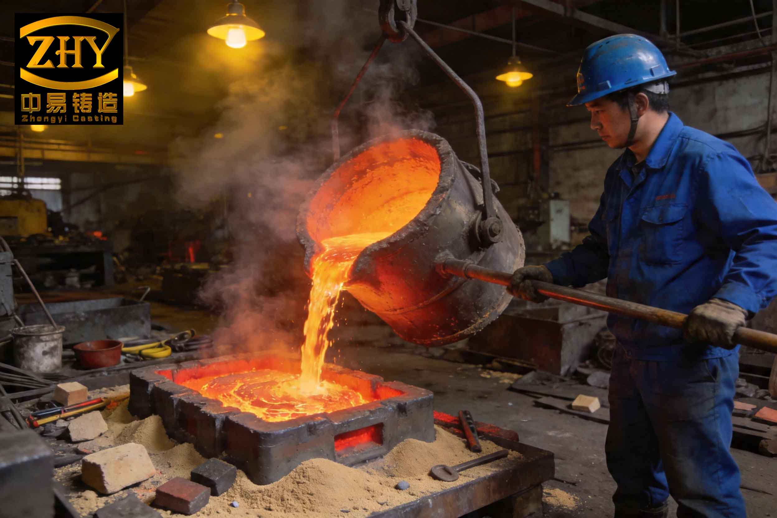
The image above provides a visual reference typical of slag inclusions encountered in practice, showing the irregular morphology and characteristic coloration. Analyzing such images forms a crucial part of the initial visual assessment phase I employ.
2. A Hierarchical Approach to Defect Discrimination
In my practice, I advocate a tiered methodology for distinguishing between slag inclusions and sand holes. This approach escalates in complexity and cost, ensuring efficient resource use.
2.1 Primary Method: Visual Inspection by Experienced Personnel
The first line of defense is trained human judgment. With accumulated experience, I and other technicians learn to recognize subtle cues. For slag inclusions, the tell-tale whitish hue, the specific surface texture resembling frozen slag, and their tendency to appear in certain thermal zones (like cope surfaces or hot spots) are key indicators. For sand holes, the darker color and the context—such as being downstream of a turbulent gate or in an area with known mold weakness—provide clues. This method is fast and cost-effective but can be subjective for ambiguous cases.
2.2 Secondary Method: Shot Blasting Test
When visual inspection is inconclusive, a simple practical test is performed. The suspect area is subjected to controlled shot blasting. As noted in the table, the behavior differs markedly. If the cavity contents are easily ejected, leaving a clean metallic surface, it is conclusively a sand hole. If the material withstands blasting and remains firmly embedded, it points strongly toward a slag inclusion. This test is reliable in about 80-90% of ambiguous cases in my experience.
2.3 Tertiary Method: Advanced Microstructural and Chemical Analysis
For the most stubborn cases, or for root cause analysis requiring definitive proof, I resort to advanced instrumental techniques. Scanning Electron Microscopy (SEM) coupled with Energy-Dispersive X-ray Spectroscopy (EDS) is my tool of choice. This allows for high-magnification observation of the defect’s morphology and quantitative elemental analysis at specific points.
The process involves:
- Sectioning the casting to obtain a sample containing the defect.
- Preparing a metallographic mount, grinding, and polishing.
- Examining under SEM to observe topography and using backscattered electron (BSE) imaging to reveal atomic number contrast.
- Performing EDS point analysis or mapping on the defect area and the surrounding matrix.
In BSE mode, phases with higher average atomic number appear brighter. Since metallic iron (Z=26) is heavier than typical slag oxides (containing O, Si, Al with lower Z), the matrix appears bright white, while slag inclusions appear dark gray or black. This provides immediate visual differentiation from sand, which, being primarily SiO₂ (Si Z=14, O Z=8), also appears dark but often with a distinct particulate structure.
The EDS data provides conclusive evidence. The quantitative atomic or weight percentages are decisive. For a classic slag inclusion rich in iron oxide, the spectrum will show a dominant Fe peak accompanied by a substantial O peak. The ratio can even be approximated. If we assume the inclusion is primarily FeO (wüstite), the theoretical weight percentage is O: 22.27%, Fe: 77.73%. For Fe₂O₃ (hematite), it is O: 30.06%, Fe: 69.94%. Measured values from EDS will be in this ballpark, possibly with additional elements like Mn, Si, or Ca. In contrast, a sand hole will yield a spectrum dominated by Si and O, with an atomic ratio close to 1:2 (for SiO₂), and minimal Fe unless there is adherent metal.
To formalize the decision logic based on EDS results, consider the following conditional criteria, where \( C_{O} \), \( C_{Fe} \), and \( C_{Si} \) are the weight percentages of Oxygen, Iron, and Silicon respectively from the defect site analysis:
$$
\text{If } \left( \frac{C_{O}}{C_{Fe}} \right) \approx 0.287 \text{ (for FeO) or } \approx 0.430 \text{ (for Fe₂O₃)} \text{ and } C_{Si} \text{ is low, classify as Slag Inclusion.}
$$
$$
\text{If } \left( \frac{C_{Si}}{C_{O}} \right) \approx 0.5 \text{ (by weight, for SiO₂) and } C_{Fe} \text{ is very low, classify as Sand Hole.}
$$
These formulas, while idealized, guide the quantitative assessment I perform on the EDS data.
3. Extended Case Study: Analysis of a Recurring Defect in a Gray Iron Cover
I recall a specific instance from a collaborative project where a foundry was producing gray iron covers using green sand molding. A persistent defect appeared on the bottom face (a last-to-solidify region) of the casting. Initial opinions among technicians were split between sand holes and slag inclusions. Simple shot blasting did not yield a unanimous verdict, as some cavities seemed partially cleansed while others remained stubborn.
My team was engaged to resolve the issue. We extracted a sample containing several typical defects. The macroscopic observation revealed clusters of small, irregular, dark-gray cavities. Under low-power stereo microscopy, the surfaces appeared rough with some granularity, but also showed hints of a layered structure.
We proceeded to SEM/EDS analysis. The SEM micrographs at 500x magnification clearly showed cavities filled with a conglomerate of particles, some blocky, some granular, with clear boundaries and evidence of detachment from the surrounding metal. The BSE image was particularly revealing. The matrix was bright, but the defect zone was predominantly dark gray, with variations in contrast suggesting multiple phases. At higher magnification, we could see transition zones where the brightness gradually decreased from the metal into the defect, indicative of diffusion and reaction layers—a common feature with slag inclusions as they interact with the solidifying metal.
We then conducted EDS point analyses. The results are summarized in the table below, which contrasts the composition of the base metal and two distinct points within the defect.
| Analysis Point | Fe (wt%) | C (wt%) | Si (wt%) | Mn (wt%) | O (wt%) | Al (wt%) | Interpretation |
|---|---|---|---|---|---|---|---|
| Base Metal (Point 1) | 94.2 | 3.1 | 2.3 | 0.4 | 0.0 | 0.0 | Typical gray iron |
| Defect – Blocky Phase (Point 2) | 64.6 | 0.0 | 0.0 | 0.0 | 35.4 | 0.0 | Iron Oxide (Fe~0.95O) |
| Defect – Granular Phase (Point 3) | 58.1 | 0.0 | 5.8 | 1.2 | 32.5 | 2.4 | Complex Silicate Slag |
The data from Point 2 is remarkably clear. The Fe:O ratio is approximately 1.83:1 by weight, which is close to the 1.78:1 ratio for FeO (or non-stoichiometric wüstite). The near absence of Si and C confirms it is not sand. Point 3 shows a more complex slag inclusion containing silicon and aluminum, likely from mold reactions or flux residues.
Based on this evidence, I conclusively diagnosed the defect as slag inclusions, specifically composed of iron oxides and complex silicates. The root cause was traced to inadequate slag removal during tapping and pouring, combined with turbulence in the gating system which emulsified the slag and carried it into the mold cavity where it was trapped in the thermal center during final solidification.
This case underscores the power of the hierarchical approach. When simpler methods faltered, the advanced SEM/EDS analysis provided unambiguous data, centering the diagnosis firmly on slag inclusions.
4. Proactive Prevention Strategies: A Foundry Engineer’s Guide
Identifying defects is only half the battle; preventing them is the ultimate goal. Based on my experience and the root causes identified, I recommend the following targeted measures. These are often most effective when implemented as part of a holistic process control system.
4.1 Prevention of Sand Holes
Since sand holes originate from the mold, strategies focus on enhancing mold integrity and handling cleanliness. I typically advocate for:
| Area of Control | Specific Action | Rationale / Theoretical Basis |
|---|---|---|
| M Sand Quality & Strength | Use high-quality, high-bonding clays (e.g., bentonite). Add cellulose or proprietary additives to improve toughness. Maintain optimal moisture and compactability. | Increases the mold’s resistance to erosion (\( \tau_s \) in erosion equation). The green compressive strength should be monitored and kept within a strict range, e.g., 1.4 – 1.8 MPa for many iron castings. |
| Molding Machine & Tooling | Regular calibration of molding machines to ensure uniform compaction. Periodic maintenance and inspection of patterns and core boxes for wear. | Prevents mismatches and low-density zones in the mold that are prone to erosion and mechanical failure. |
| Mold/Core Handling | Thorough cleaning of mold cavities and runners before closing using effective blow-off systems. Inspect sand cores for surface finish; reject friable ones. | Eliminates loose sand that could be directly incorporated into the metal stream. |
| Gating & Pouring Design | Design gating systems to minimize turbulent impingement on mold walls. Use choke areas to control velocity. Consider the use of ceramic filters in the runner. | Reduces the dynamic pressure (\( \rho U^2 \)) acting on the mold wall, directly lowering the erosion rate \( \dot{E} \). Filters can also trap any loose sand particles carried by the metal. |
| Process Design | Design adequate clearances for core setting to prevent “crush” or rubbing that generates loose sand. | Prevents a direct source of sand introduction during mold assembly. |
4.2 Prevention of Slag Inclusions
Combating slag inclusions requires control over the molten metal’s cleanliness from furnace to mold. My standard protocol emphasizes:
| Area of Control | Specific Action | Rationale / Theoretical Basis |
|---|---|---|
| Charge Materials | Use clean, rust-free, and oil-free scrap and returns. Pre-treat charge to remove contaminants. | Minimizes the initial oxide load introduced into the melt, reducing the source term for slag formation. |
| Melting & Slag Management | Employ proper fluxing and slagging-off practices during melting. Ensure a reducing atmosphere where possible. Allow sufficient holding time after melting for slag agglomeration and flotation. | Promotes the coalescence of fine slag particles into larger ones, increasing their rise velocity \( v \) according to Stokes’ law (\( v \propto r^2 \)), thus enhancing removal efficiency before tapping. |
| Ladle & Transfer Operations | Pre-heat ladles to prevent thermal shock and metal oxidation. Keep ladle linings clean and in good repair. Use teapot spout or bottom-pour ladles to separate metal from slag during transfer. | Prevents ladle-generated slag and re-oxidation. Teapot ladles draw metal from below the slag layer, physically blocking its transfer. |
| Pouring & Gating Systems | Use pouring basins with dams and skimmers. Employ ceramic foam filters in the gating system. Design runner systems to be “slag-traps” with abrupt upward turns. Maintain a full, non-turbulent pouring stream. | Filters physically intercept slag particles. Slag traps utilize density difference; slag floats to the top of an enlarged runner section. A full stream minimizes air entrainment and re-oxidation. The efficiency of a filter can be modeled by capture mechanisms like interception and cake filtration. |
| In-Mold Treatments | Add inert gas bubbling or rotary degassing if feasible for higher-value castings. Use mold coatings that are less reactive. | Further reduces dissolved gases and non-metallic inclusions. Less reactive coatings minimize mold-metal reaction slag. |
It is critical to understand that preventing slag inclusions is often about managing the entire fluid flow and thermal history. The probability of a slag particle being trapped, \( P_e \), is minimized by allowing ample time for flotation (low \( V_s \) during early solidification) and by using filtration to physically remove particles. The combined effectiveness \( E_{total} \) of multiple slag reduction steps can be thought of as a product of individual efficiencies:
$$ E_{total} = (1 – \eta_1)(1 – \eta_2)…(1 – \eta_n) $$
where \( \eta_i \) is the removal efficiency of step \( i \) (e.g., ladle skimming, filtering). This multiplicative relationship highlights why a multi-pronged approach is essential for robust prevention of slag inclusions.
5. Broader Context and Advanced Considerations
Beyond the immediate discrimination and prevention, understanding slag inclusions and sand holes connects to larger themes in casting science. In my research and practice, I have explored several advanced aspects.
5.1 Thermodynamics of Slag Formation
The formation of oxide-based slag inclusions is governed by thermodynamics. For the oxidation of iron in the melt:
$$ \text{Fe (l)} + \frac{1}{2}\text{O}_2 (g) \rightleftharpoons \text{FeO (l/s)} $$
The equilibrium constant is \( K = \frac{a_{FeO}}{a_{Fe} \cdot P_{O_2}^{1/2}} \), where \( a \) denotes activity. In the presence of other elements like Si and Mn, complex silicates like fayalite (2FeO·SiO₂) can form, which have lower melting points and are more likely to remain fluid and entrap. The activity of oxygen in the melt, often measured by oxygen probes, is a direct indicator of the driving force for oxide slag inclusion formation. Maintaining a low dissolved oxygen level is a key metallurgical goal.
5.2 Statistical Process Control (SPC) for Defect Reduction
Implementing SPC on key parameters can proactively reduce both defect types. For sand holes, control charts for green compression strength, moisture content, and loss-on-ignition are vital. For slag inclusions, data on metal temperature, holding time, and filter usage rates can be monitored. Correlation analysis can reveal hidden relationships. For instance, I have modeled defect rate \( D \) as a function of multiple variables:
$$ D_{slag} = \alpha_0 + \alpha_1(T_{tap}) + \alpha_2(t_{hold}) + \alpha_3(U_{pour}) + \epsilon $$
where \( \alpha_i \) are coefficients, \( T_{tap} \) is tapping temperature, \( t_{hold} \) is holding time, \( U_{pour} \) is pouring velocity, and \( \epsilon \) is error. Regression models help in setting optimal process windows.
5.3 The Role of Simulation Software
Modern casting simulation software is an invaluable tool in my defect prevention arsenal. These programs can model mold filling and solidification, predicting areas of high velocity (potential sand erosion zones) and last-to-solidify regions (potential sinks for slag inclusions due to inverse segregation). By virtually testing different gating designs, one can optimize for laminar flow and effective slag trapping before producing a single physical mold. The software often solves the Navier-Stokes equations for fluid flow coupled with heat transfer:
$$ \rho \left( \frac{\partial \mathbf{u}}{\partial t} + \mathbf{u} \cdot \nabla \mathbf{u} \right) = -\nabla p + \nabla \cdot (\mu \nabla \mathbf{u}) + \rho \mathbf{g} $$
$$ \rho C_p \left( \frac{\partial T}{\partial t} + \mathbf{u} \cdot \nabla T \right) = \nabla \cdot (k \nabla T) + \dot{q} $$
where \( \mathbf{u} \) is velocity, \( p \) pressure, \( \mu \) viscosity, \( T \) temperature, \( C_p \) specific heat, \( k \) thermal conductivity, and \( \dot{q} \) latent heat release. These simulations visually highlight turbulence and thermal gradients, guiding preemptive design changes.
5.4 Economic Impact and Quality Cost
Misdiagnosing a slag inclusion as a sand hole, or vice versa, leads to incorrect corrective actions, wasting time and resources. The cost of rework, scrap, and delayed shipments can be substantial. Implementing the hierarchical discrimination approach and the preventive measures outlined has a direct positive impact on the cost of quality (COQ), reducing internal and external failure costs. A focus on preventing slag inclusions, given their often-subtle origin in metal treatment, can yield particularly high returns by improving the consistency and reliability of the cast metal itself.
In conclusion, through a combination of fundamental understanding, systematic analysis protocols, and proactive process engineering, the confusion between slag inclusions and sand holes in green sand casting can be effectively resolved. My experience reaffirms that a deep dive into the characteristics of slag inclusions, supported by both simple tests and sophisticated instrumentation, is essential for accurate diagnosis. Subsequently, implementing targeted, science-based prevention strategies significantly enhances product quality and operational efficiency in the foundry. The journey from defect discovery to elimination is a testament to applied materials science and rigorous quality management, with the term ‘slag inclusions’ serving as a constant reminder of the critical need for molten metal cleanliness throughout the casting process.