
In the realm of manufacturing complex and heavy-duty components, such as those used in machine tools and railway systems, the quality and reliability of sand casting products are paramount. As an engineer specializing in casting process design, I am often confronted with the challenge of producing large, structurally intricate parts like upper rotary discs, which are typically made from high-strength gray iron such as HT300. These components must exhibit excellent mechanical strength, stability, and wear resistance to withstand significant static and dynamic loads. The inherent complexity of their geometry—featuring uneven wall thickness, numerous bores, and deep recesses—makes them particularly susceptible to founding defects like shrinkage porosity and cavities, which can severely compromise their performance in service.
The traditional approach to casting process design relies heavily on empirical knowledge and iterative physical prototyping, which is both time-consuming and costly. Today, the integration of Computer-Aided Engineering (CAE) tools has revolutionized this field. Numerical simulation allows for a virtual analysis of the entire casting process—filling, solidification, and cooling—enabling the prediction and mitigation of defects before a single mold is made. This digital foundry approach is indispensable for advancing towards high-precision, high-quality, and efficient production of sand casting products. In this detailed analysis, I will walk through the complete process of optimizing the casting process for an HT300 upper rotary disc using numerical simulation, demonstrating how strategic modifications can effectively eliminate critical defects.
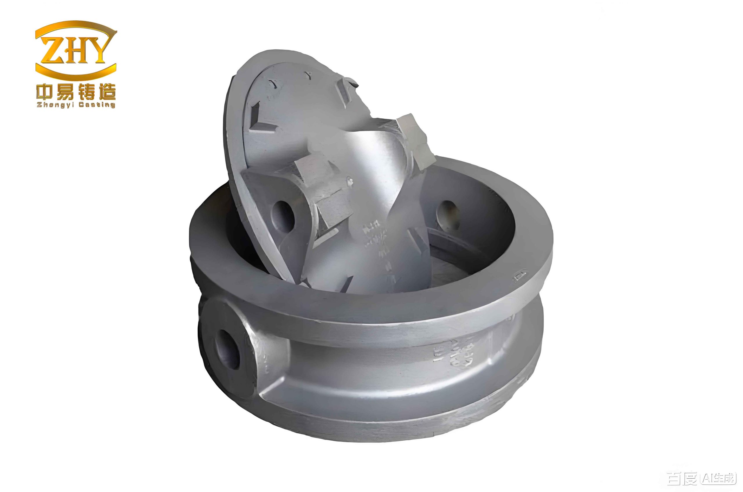
The component in question is a large upper rotary disc. Its primary functions are to support the weight of a machine tool assembly and to serve as a guide rail for a cutting tool carriage. Its complex geometry, with a pronounced variation in section thickness, presents a classic foundry challenge. The critical quality requirements mandate that the large planar surfaces must be free from defects like sand inclusions and gas holes, and the internal soundness must be high, with minimal shrinkage defects. Any significant porosity in the load-bearing sections or around the bearing bores could lead to catastrophic failure under load or oil leakage. Therefore, the goal is to design a process that ensures directional solidification, feeding the thick sections effectively to prevent the formation of isolated liquid pools that result in shrinkage.
My initial step involved a comprehensive structural analysis. The disc’s dimensions are substantial, and its weight is significant. The wall thickness varies from a maximum in the hub and rib areas to a minimum in the flange sections. A summary of the key geometric and material parameters is presented below.
| Parameter | Value / Description |
|---|---|
| Material | Gray Cast Iron HT300 |
| Nominal Density | 7.3 g/cm³ |
| Approximate Mass | 502 kg |
| Overall Dimensions | 1281 mm x 1270 mm x 101 mm |
| Max Wall Thickness | 113 mm |
| Min Wall Thickness | 15 mm |
| Key Quality Requirement | Minimal internal shrinkage porosity & sound critical surfaces. |
Initial Process Design and Numerical Simulation Setup
Based on standard foundry principles for sand casting products, the initial process was designed. To promote a stable fill and minimize turbulence, a bottom-gating system was selected. The system consisted of one sprue, two runners, and seven ingates, with a choke area at the sprue base to establish a favorable pressure gradient and reduce metal aspiration. The gating ratio was designed to be pressurized. Furan no-bake sand was selected for both the mold and cores due to its good dimensional stability and collapsibility. The initial layout placed the part with its larger, more massive sections oriented towards the top of the mold, anticipating that these would require feeding.
For the virtual analysis, a dedicated casting simulation software (ProCAST) was employed. The 3D model of the part, including the gating system, was meshed. A virtual mold enclosure was defined with dimensions sufficiently large to prevent unrealistic boundary effects on the thermal calculations. Accurate thermophysical property data for HT300, the molding sand, and other materials like chills or insulating sleeves are critical for reliable simulation results. The heat transfer across interfaces (metal-sand, metal-chill) was defined using validated coefficients. The initial pouring conditions were set as follows.
| Process Parameter | Initial Value |
|---|---|
| Pouring Temperature | 1370 °C |
| Calculated Pouring Time | 47 s |
| Mold Material | Furan Resin Sand |
| Heat Transfer Coefficient (Metal-Sand) | 500 W/(m²·K) |
The filling analysis confirmed that the bottom-gating system filled the mold cavity smoothly without excessive surface turbulence or premature freezing. The metal front progressed evenly from the bottom upwards, taking approximately 45 seconds in the simulation, which aligned well with the designed pouring time. This validated the hydraulic design of the gating system for this class of sand casting products.
Analysis of Solidification and Defect Prediction in the Initial Design
The core of the optimization lies in the solidification analysis. The software solves the energy equation to track the evolution of the temperature field and the solid fraction over time. For a gray iron, the solidification involves the evolution of graphite, which is accompanied by an expansion that can counter-act the shrinkage of the austenite. However, in heavy sections, this self-feeding effect can be insufficient, leading to macro- and micro-shrinkage. The governing heat transfer equation during solidification is:
$$
\rho c_p \frac{\partial T}{\partial t} = \nabla \cdot (k \nabla T) + \rho L \frac{\partial f_s}{\partial t}
$$
where $ \rho $ is density, $ c_p $ is specific heat, $ T $ is temperature, $ t $ is time, $ k $ is thermal conductivity, $ L $ is latent heat, and $ f_s $ is solid fraction.
The simulation of the initial process revealed a problematic solidification pattern. The temperature gradient and the solidification sequence were not controlled. The results clearly showed that the last regions to solidify were isolated within the thick sections of the casting itself—specifically at the hub and the intersections of major ribs. These isolated hot spots, devoid of a feeding path, culminated in the prediction of significant shrinkage porosity. The defect prediction module, often based on criteria like the Niyama criterion or simply tracking the last points to reach solidus temperature, highlighted these areas in red. This confirmed the theoretical concern: without adequate risers, the volumetric contraction during solidification could not be compensated, leaving voids within the critical structural zones of the sand casting products. A summary of the major defect zones is shown below.
| Location of Predicted Defect | Type of Defect | Severity |
|---|---|---|
| Central Hub Region | Macro Shrinkage Cavity | High |
| Junction of Main Ribs | Shrinkage Porosity | Medium-High |
| Upper Surface of Thick Sections | Micro Porosity | Medium |
Process Optimization Strategy and Implementation
The simulation diagnosis provided a clear directive for optimization: to achieve directional solidification towards strategically placed risers. The goal is to make the risers the last parts of the total volume (casting + risers) to solidify, ensuring they can feed liquid metal to compensate for shrinkage in the casting. The optimization involved two key changes:
- Riser Design and Placement: Based on the identified hot spots, a combination of top risers was designed. For the massive central hub, a large necked-down top riser was specified. For other isolated thick sections on the upper face, smaller blind risers were placed. Their dimensions were calculated using modulus methods, ensuring their solidification time was longer than that of the casting sections they were intended to feed. The risers were positioned on non-critical or machined surfaces for easy removal later.
- Gating System Modification: To improve temperature distribution and better integrate with the new riser layout, the gating was switched to a top-pouring system. This change helps establish a more favorable thermal gradient from the bottom of the casting up towards the risers at the top during the initial stages of solidification. The new system was designed to remain turbulent-free.
The new riser dimensions and the revised gating parameters are summarized in the following tables.
| Riser Type | Diameter (mm) | Height (mm) | Neck Diameter (mm) | Purpose |
|---|---|---|---|---|
| Necked Top Riser | 180 | 300 | 90 | Feed central hub |
| Blind Riser | 80 | 180 | N/A | Feed isolated rib junctions |
| Component | Cross-Sectional Area (cm²) | Function in Revised Layout |
|---|---|---|
| Sprue (1x) | 38.5 | Delivers metal from pouring basin |
| Runner (1x) | 33.0 | Distributes metal horizontally |
| Ingate (4x) | 31.7 | Controls fill rate into mold cavity |
Results of the Optimized Process Simulation
The modified process model was simulated under the same boundary conditions. The filling analysis for the top-gated system showed a different but equally acceptable fluid flow pattern, with rapid coverage of the upper sections and no cold shuts. The crucial solidification analysis, however, showed a dramatic improvement.
The temperature gradient was now clearly oriented. The solidification sequence began in the thinner, lower sections of the disc and the extremities. The solidification fronts then progressed upwards and inwards towards the strategically placed risers. Finally, the thermal ends were located squarely within the riser bodies. This is the hallmark of a sound casting process design for sand casting products. The defect prediction results confirmed this successful directional solidification. The previously highlighted shrinkage zones in the casting body were now absent. The software now indicated that the only significant shrinkage cavities were contained within the risers themselves, which is the intended function of a riser—to act as a sacrificial reservoir of liquid metal.
The effectiveness of the optimization can be quantified by comparing the defect volume predicted inside the functional part of the casting before and after the changes. While the simulation provides relative metrics, the visual and qualitative difference is conclusive.
| Metric | Initial Process | Optimized Process |
|---|---|---|
| Major Shrinkage in Critical Hub | Present (Large Cavity) | Absent (Transferred to Riser) |
| Porosity in Rib Junctions | Multiple Locations | Absent |
| Defect Location | Within Casting Body | Confined to Riser Volumes |
| Expected Internal Soundness | Poor – Unacceptable for Service | High – Meets Specification |
Conclusion and Broader Implications
This systematic case study underscores the transformative power of numerical simulation in the foundry industry, particularly for complex sand casting products. Beginning with an initial design that would have led to defective castings, the use of CAE tools allowed for a precise diagnosis of the problem—uncontrolled solidification leading to isolated hot spots. The solution, informed by simulation feedback, involved a strategic redesign incorporating properly sized and placed risers, along with a complementary gating modification to establish a favorable thermal gradient.
The final simulated results demonstrated that the optimized process successfully achieved directional solidification, effectively transferring the shrinkage defects from the critical areas of the HT300 upper rotary disc into the sacrificial risers. This virtual optimization process saves immense time and cost compared to the traditional trial-and-error method on the shop floor. It minimizes material waste, energy consumption, and ensures right-first-time production. For foundries aiming to produce high-integrity, heavy-section castings, the integration of numerical simulation into the process design workflow is not merely an advantage but a necessity. It provides a deep, physics-based understanding of the casting process, enabling engineers to confidently design robust methods that yield reliable, high-quality sand casting products capable of meeting the stringent demands of modern machinery and infrastructure.