
In the realm of heavy industrial manufacturing, particularly for mining equipment, the integrity of critical components is paramount. As a foundry engineer specializing in steel castings for mining machinery, I have spent considerable time analyzing and addressing the persistent challenges in producing hydraulic support sockets via sodium silicate-bonded sand molding. These sockets, typically crafted from low-carbon alloy steel like ZG30Cr06, bear immense strata pressure in coal mines. Their failure can compromise entire support systems, posing severe safety risks. Therefore, a deep understanding and proactive management of sand casting defects are not just procedural but essential for reliability. This article delves into the common sand casting defect types encountered—shrinkage cavities, gas porosity, and metal penetration—and presents a detailed, first-person perspective on their root causes, theoretical underpinnings, and comprehensive preventive measures, incorporating quantitative models and structured guidelines.
The prevalence of sand casting, accounting for approximately 90% of all cast components, underscores its industrial significance. In our operations, we primarily employ CO2-hardened sodium silicate sand. While offering excellent flowability and rapid hardening, this system presents distinct challenges, notably poor collapsibility and significant resistance to metal contraction during solidification. Coupled with the high shrinkage tendency of low-carbon alloy steels, these factors create a fertile ground for various sand casting defects. The journey toward defect-free castings begins with a meticulous dissection of each flaw.
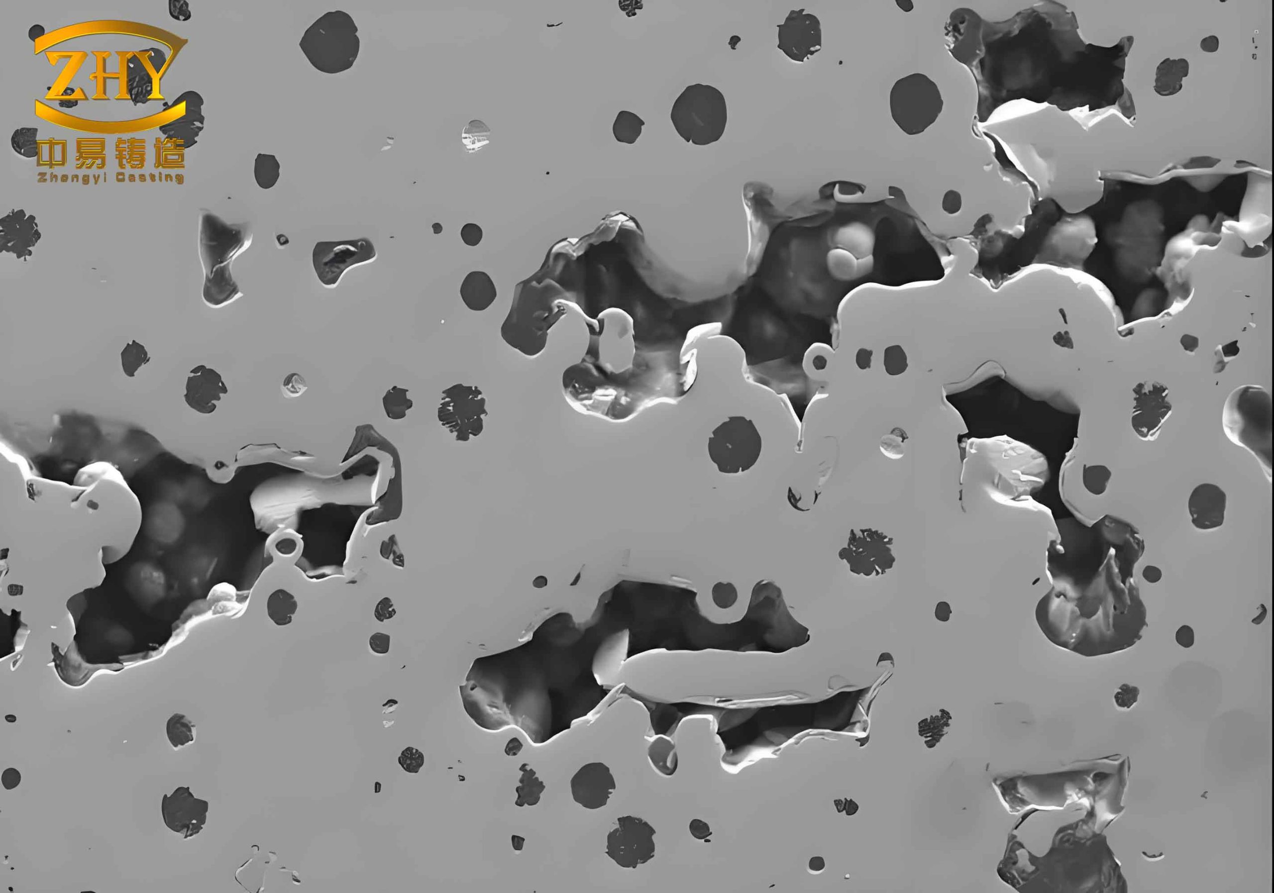
1. In-Depth Analysis of Shrinkage Cavity Defects
Shrinkage cavities rank among the most critical sand casting defects in socket production. These are macroscopic voids with rough, dendritic surfaces that form in the final freezing zones or hot spots of a casting due to inadequate liquid metal feed during solidification. They severely reduce the load-bearing cross-section and mechanical strength.
The formation is fundamentally governed by solidification dynamics. The volumetric shrinkage during the phase change from liquid to solid must be compensated by a continuous feed of molten metal from the risers. For a steel casting, the total volume change can be modeled. The solidification shrinkage, $\beta$, is a key parameter:
$$\beta = \frac{V_l – V_s}{V_l} \times 100\%$$
where $V_l$ is the liquid volume and $V_s$ is the solid volume at the freezing point. For typical cast steels, $\beta$ ranges from 3% to 6%. The feeding requirement, $V_f$, to prevent a shrinkage cavity in a specific region is:
$$V_f = \beta \cdot V_c$$
where $V_c$ is the volume of the isolated thermal zone.
The primary causes for shrinkage cavity formation in sockets are multifaceted:
- Impeded Feeding Paths: The socket’s cruciform rib structure often creates isolated thermal sections. If the feeding channels through these ribs are prematurely blocked by solidified metal, the interior sections become unfed, leading to shrinkage porosity or cavities.
- Suboptimal Riser Design: The effectiveness of a riser is governed by its modulus ($M_R$, volume-to-surface area ratio) relative to the casting’s modulus ($M_C$). A classic criterion for effective feeding is:
$$M_R \geq 1.2 \times M_C$$
Inadequate riser diameter or height fails to maintain a thermal gradient sufficient for directional solidification toward the riser. - Elevated Pouring Temperature: While necessary for fluidity, excessive superheat increases the total contraction and can promote gas dissolution, leading to combined gas-shrinkage holes. The thermal gradient is less steep, widening the mushy zone and complicating feeding.
- Premature Riser Freezing: If the riser loses heat too quickly, its metal solidifies before the casting, causing a “reverse feeding” phenomenon where the casting feeds the riser, guaranteed to create a cavity in the casting.
A summary of targeted strategies to combat this sand casting defect is presented in Table 1.
| Cause Category | Preventive Action | Quantitative Guideline / Principle |
|---|---|---|
| Feeding Path Obstruction | Optimize casting geometry with graded sections; use chills to create directional solidification. | Ensure solidification gradient > 10°C/cm toward riser. Use modulus calculations to identify hot spots. |
| Riser Inefficiency | Employ exothermic/insulating riser sleeves; use blind risers with atmospheric pressure cores. | Design riser modulus: $M_R \geq 1.2M_C$. Riser volume $V_R \geq \frac{\beta}{η} V_F$, where η is riser efficiency (≈14% for open sand risers, up to 67% for exothermic). |
| Pouring Parameters | Adopt “high temperature melting, low temperature pouring”. Control pouring speed. | For ZG30Cr06, aim for pouring temp 1540-1580°C (as measured in ladle). Use step-gate systems to control fill rate. |
| Riser Performance | Implement hot topping practice: feed riser with hotter metal post-pour, cover with exothermic compound. | Maintain riser open time $t_{open} > t_{casting\ freeze}$ of critical section. Use late-stage inoculation to prolong fluidity. |
2. Systematic Examination of Gas Porosity Defects
Gas porosity, another pervasive sand casting defect, manifests as spherical or elongated smooth-walled cavities within or just below the casting skin. These defects drastically reduce fatigue strength and pressure tightness. Based on origin, gas porosity is classified into three types, with two being predominant in our practice.
2.1 Precipitation (Micro) Porosity
This sand casting defect arises from the decreased solubility of gases like hydrogen and nitrogen in steel during cooling and solidification. The dissolved gas content in liquid steel follows Sieverts’ law:
$$C_g = k_g \sqrt{P_g}$$
where $C_g$ is the dissolved gas concentration, $k_g$ is the equilibrium constant (temperature-dependent), and $P_g$ is the partial pressure of the gas above the melt. Upon solidification, the solubility drops precipitously (e.g., for hydrogen in iron, from ~28 ppm in liquid to ~8 ppm in solid at the melting point). The excess gas forms bubbles. If these cannot nucleate and float out in the viscous semi-solid, they remain trapped as fine, dispersed pores.
2.2 Invasive (Macro) Porosity
This form of sand casting defect occurs when gases from the mold cavity or sand core are forced into the solidifying metal. The primary source is the thermal decomposition of the sodium silicate binder and any moisture. The gas generation pressure, $P_{gen}$, must overcome the sum of the metallostatic pressure ($ρ_m g h$) and the capillary pressure at the metal-mold interface to invade. The condition for invasion is approximately:
$$P_{gen} > ρ_m g h + \frac{2γ \cosθ}{r}$$
where $ρ_m$ is metal density, $g$ is gravity, $h$ is metal head height, $γ$ is metal surface tension, $θ$ is contact angle, and $r$ is the pore radius in the sand. Poor venting in deep pockets like socket ears exacerbates this issue.
Common operational lapses leading to this sand casting defect include inadequate mold/core venting, insufficient deoxidation of steel, and turbulent metal flow during pouring which entraps air. Table 2 consolidates the control measures.
| Porosity Type | Root Cause | Preventive Measures & Technical Protocols |
|---|---|---|
| Precipitation Porosity | High gas content in melt (H₂, N₂). | Use dry, rust-free charge materials; pre-heat ladles and tools to >600°C. Implement vacuum degassing or argon flushing if feasible. |
| Insufficient deoxidation. | Final deoxidation with Aluminum: Add 0.03-0.06% Al as pure Al-wire or shot. For secondary tapping, ensure Al addition in ladle precedes tapping. | |
| Rapid cooling rate. | Modify thermal modulus of mold to allow slower solidification in heavy sections, enabling gas diffusion and bubble floatation. | |
| Invasive Porosity | High gas pressure from mold/core. | Limit sodium silicate addition to <8% by weight. Use low-moisture sands (<2%). Ensure thorough CO2 gassing to form a stable silica gel matrix. |
| Poor mold permeability and venting. | Optimize sand grain fineness (AFS 50-70). Install vent channels and pierce copious vent holes (~4-6 holes per dm²) in mold cores. Apply mold coatings with high permeability. | |
| Turbulent filling & air entrapment. | Design gating system with choke at bottom, using sprue well, dam, and filters. Maintain a positive and steady pressure head. Pouring time $t_p$ should satisfy: $t_p ≈ k \sqrt{W}$, where $W$ is casting weight (kg) and $k$ is an empirical factor (1.5-2.5 for steel). |
3. Metal Penetration (Burning-on) as a Surface Sand Casting Defect
Metal penetration, often termed burning-on or severe sand sintering, is a sand casting defect where a tough, adherent layer of fused sand and metal oxides coats the casting surface. It complicates cleaning and impairs weldability for subsequent assembly.
The mechanism is primarily physical penetration driven by capillary forces. The pressure ($P_{pen}$) forcing metal into sand interstices is:
$$P_{pen} = P_{metal} + P_{capillary} = ρ_m g h + \frac{2γ_{lv} \cosθ}{d_p}$$
where $d_p$ is the average pore diameter between sand grains. Penetration occurs when $P_{pen}$ exceeds the resisting gas pressure in the pores. Key contributing factors include:
- Low Sand Compaction: High porosity (low green density) increases pore size $d_p$, reducing capillary resistance and facilitating infiltration.
- Excessive Pouring Temperature: High superheat lowers metal viscosity ($η$) and surface tension ($γ_{lv}$), enhancing penetration depth $L$ which can be approximated by:
$$L ≈ \sqrt{\frac{d_p γ_{lv} \cosθ \cdot t}{4η}}$$
where $t$ is the contact time. - Inadequate Refractoriness: Low-purity sands or excessive binder content lower the sintering point of the sand surface, promoting chemical bonding with metal oxides.
Table 3 outlines a multi-pronged approach to mitigate this surface-affecting sand casting defect.
| Focus Area | Specific Action | Technical Specification / Rationale |
|---|---|---|
| Molding Sand Properties | Use high-purity silica sand with high sintering point (>1450°C). Control binder content. | SiO₂ content >98%, AFS GFN 55-65. Sodium silicate addition: 5-7.5%. Clay content <1%. |
| Apply refractory mold/coating. | Spray or brush zircon-based or graphite-based coating (density ~1.8 g/cm³) to create a thermal barrier. | |
| Mold Compaction | Achieve uniform and high mold hardness. | Aim for mold hardness 85-95 on B-scale for machine molding. Ensure uniform jolting/squeezing. |
| Process Parameters | Lower pouring temperature within fluidity limits; reduce pouring speed. | Target the lower end of the pouring temperature range (e.g., 1540°C). Use gating ratio (ΣA_choke : ΣA_runner : ΣA_gate) of 1 : 1.5 : 2 for pressurized flow to minimize erosion. |
| Mold Cleanliness | Thoroughly clean mold cavity before closing. | Use compressed air and vacuum systems to remove loose sand after mold assembly. |
4. Integrated Quality Assurance and Modern Foundry Techniques
Addressing these sand casting defects in isolation is insufficient; a holistic, process-controlled approach is vital. Modern foundry science leverages computational tools to predict and preempt defects.
Solidification Simulation: Software based on finite element or finite volume methods solves the heat transfer equation during casting:
$$ρ c_p \frac{\partial T}{\partial t} = \nabla \cdot (k \nabla T) + ρ L \frac{\partial f_s}{\partial t}$$
where $ρ$ is density, $c_p$ is specific heat, $k$ is thermal conductivity, $L$ is latent heat, and $f_s$ is solid fraction. These simulations visually predict shrinkage cavity locations, allowing for iterative riser and chill placement optimization before making any physical mold.
Gating System Design: Computational Fluid Dynamics (CFD) models the filling process, calculating velocity fields, temperature loss, and potential areas for air entrainment or mold erosion. This directly informs designs to minimize gas porosity and metal penetration sand casting defects.
Process Parameter Optimization: Statistical methods like Design of Experiments (DOE) and Response Surface Methodology (RSM) can model the relationship between input variables (sand moisture, binder content, pouring temp, etc.) and output defect rates. For instance, a model for total defect score $Y$ might be:
$$Y = β_0 + β_1X_1 + β_2X_2 + β_{12}X_1X_2 + β_{11}X_1^2 + β_{22}X_2^2 + ε$$
where $X_1$ is pouring temperature and $X_2$ is sand compactness. This enables finding robust operating windows.
Implementing a rigorous metallurgical control plan is also crucial. This includes:
- Charge Design: Precise control of raw material quality to limit gas-generating elements.
- Melt Treatment: Effective slag removal, deoxidation, and grain refinement. The final aluminum content should be verified via spectrometer analysis.
- Mold Quality Control: Regular testing of sand properties (permeability, compressive strength, moisture content, LOI) and mold hardness mapping.
5. Concluding Synthesis
The battle against sand casting defects in critical components like hydraulic support sockets is continuous and demands a blend of empirical knowledge, theoretical understanding, and modern technology. Shrinkage cavities, gas porosity, and metal penetration—each distinct in origin—require tailored, scientifically-grounded countermeasures. The core philosophy must shift from reactive correction to proactive prevention. By mastering solidification principles through modulus calculations, controlling gas generation and venting via permeability management and deoxidation practices, and resisting metal penetration through refractory engineering and parameter control, foundries can achieve significant quality leaps.
Ultimately, the integration of advanced simulation and statistical process control into traditional craft elevates the entire manufacturing process. It reduces the reliance on trial-and-error, minimizes scrap and rework, and delivers castings with predictable, high-integrity properties. For industries where component failure carries severe consequences, such relentless focus on understanding and eliminating every potential sand casting defect is not merely a technical pursuit but a fundamental commitment to safety and operational excellence. The journey toward zero-defect casting is complex, but with systematic analysis and the application of engineering principles outlined here, it is an entirely achievable goal.