
As a foundry engineer specializing in heavy-section castings, I have been involved in numerous projects involving ductile cast iron components. The production of a large sand suction pump body, weighing approximately 46,600 kg and with complex geometries, presents significant challenges due to its demanding service environment. This pump operates in harsh conditions, such as river dredging and coastal reclamation, where it handles abrasive slurries with solid contents exceeding 40%. Therefore, the casting must be free from defects like shrinkage porosity and looseness to ensure structural integrity and prevent fluid leakage. In this article, I will detail our comprehensive approach to designing and implementing a casting process for this ductile cast iron pump body, emphasizing the use of expanded polystyrene (EPS) mold patterns, advanced gating systems, and meticulous metallurgical controls. Throughout this discussion, the term “ductile cast iron” will be frequently referenced, as it is the core material that dictates the process parameters and performance outcomes.
The pump body, with overall dimensions of 5,800 mm × 3,480 mm × 2,200 mm and a nominal wall thickness of 75 mm (reaching up to 355 mm at critical sections), is cast in ductile cast iron grade QT500-7. Its irregular shape, which includes numerous curved surfaces and a series of threaded holes on the top face for pump cover assembly, necessitates a precision molding technique. After thorough analysis, we opted for a no-bake furan resin sand process combined with an EPS mold—commonly known as lost foam or “保模” casting. This method eliminates the need for draft angles and complex parting lines, but it introduces challenges such as poor surface finish due to inadequate sand compaction and potential sand inclusion during pouring. Our goal was to overcome these hurdles through meticulous design and process optimization.
In the EPS mold fabrication, we started by adding machining allowances and a casting shrinkage allowance of 1.5% to the component’s 3D model. The mold was segmented into multiple blocks to facilitate CNC machining and wire cutting from foam boards, ensuring dimensional accuracy upon assembly. After bonding the segments, we applied two coats of graphite-based paint via brushing, each layer approximately 0.2 mm thick, to enhance surface smoothness and resist sand erosion during pouring. This step is crucial for maintaining the integrity of the ductile cast iron casting’s surface.
For the gating system design, we employed a bottom-gated two-tier step gating arrangement to ensure smooth filling and minimize turbulence. The lower system handles initial mold filling, while the upper gates, positioned 1,740 mm from the bottom, serve as buffers and facilitate core placement verification. The metallostatic pressure head \( H_p \) is calculated using the formula:
$$ H_p = H_{\text{flask}} + H_{\text{pouring cup}} – \frac{C}{2} $$
where \( H_{\text{flask}} \) is the flask height, \( H_{\text{pouring cup}} \) is the pouring cup height, and \( C \) is the casting height. The pouring time \( t \) for this heavy ductile cast iron component is derived from empirical relations:
$$ t = \sqrt[3]{G_L} $$
with \( G_L \) representing the total poured weight in kilograms. The choke area \( A_{\text{choke}} \) of the gating system is determined by:
$$ A_{\text{choke}} = \frac{G_L}{\rho \cdot \mu \cdot t \cdot \sqrt{2g H_p}} $$
where \( \rho = 7.3 \times 10^{-6} \, \text{kg/mm}^3 \) for ductile cast iron, \( \mu = 0.4 \) is the flow coefficient, and \( g = 9.8 \, \text{m/s}^2 \). Since we used three ladles for pouring, the choke area was distributed accordingly. The final dimensions of the sprue, runners, and ingates were scaled as: \( A_{\text{sprue}} = A_{\text{choke}} / 0.8 \), \( A_{\text{runner}} = A_{\text{sprue}} \times 1.2 \), and \( A_{\text{ingate}} = A_{\text{sprue}} \times 0.8 \). Below is a table summarizing the key gating parameters for this ductile cast iron pump body:
| Parameter | Value | Unit |
|---|---|---|
| Total Pouring Weight (\( G_L \)) | 48,000 | kg |
| Calculated Pouring Time (\( t \)) | ~180 | s |
| Metallostatic Head (\( H_p \)) | 2,500 | mm |
| Choke Area (\( A_{\text{choke}} \)) | 4,200 | mm² |
| Sprue Diameter | 80 | mm |
| Number of Ingates | 12 | – |
To address the thick sections and prevent shrinkage defects inherent in ductile cast iron, we incorporated both external and internal chills. External chills, made of cast iron, were placed around the pump cover mating face and bearing housing areas to accelerate cooling. For the core thickness exceeding 300 mm, we used shaped internal chills to reduce the solidification time below 50 minutes, thereby preserving a high nodularity above 80%. The modulus \( M \) of a section, critical for chill design, is given by:
$$ M = \frac{V}{A} $$
where \( V \) is volume and \( A \) is cooling surface area. For sections with \( M > 9 \, \text{cm} \), internal chills are essential to avoid graphite degeneration in ductile cast iron.
Riser design is paramount for feeding ductile cast iron due to its higher shrinkage volume compared to gray iron. We positioned six Ø180 mm insulated sleeve risers on the bearing seat faces and two Ø140 mm conventional risers on the footing pads. The riser volume \( V_r \) must satisfy the feeding demand:
$$ V_r \geq \frac{V_c \cdot \alpha}{\eta} $$
where \( V_c \) is the casting volume, \( \alpha = 4\% \) is the volumetric shrinkage for ductile cast iron, and \( \eta = 0.15 \) is the riser efficiency. Venting channels were added at high points and along ribs to exhaust gases during pouring, ensuring a sound ductile cast iron structure.
In the molding stage, we used furan resin sand with a 1.2% resin addition. The process involved building the mold in four sections to allow inspection of core fits. Six cores were produced, with the largest one incorporating a cast core grid for strength, while others used welded grids of 50 mm × 60 mm steel. All cores were coated with zircon-based paint at a Baumé density of 65–70. To prevent mold wall movement, we installed wooden and welded barriers with sodium silicate sand backings, along with anti-swelling steel plates on the sides.
The spheroidization and inoculation treatments are critical for achieving the desired microstructure in ductile cast iron. We employed a pre-conditioning step by adding 0.4% pre-treatment agent to the base iron to enhance nucleation. The composition of the base iron before treatment is shown in the table below:
| Element | Range (wt%) |
|---|---|
| Carbon (C) | 3.4–3.5 |
| Silicon (Si) | 1.5–1.6 |
| Manganese (Mn) | 0.35–0.45 |
| Phosphorus (P) | ≤ 0.04 |
| Sulfur (S) | ≤ 0.03 |
For spheroidization, we used 1.05% DY-7F heavy rare-earth magnesium ferrosilicon alloy, followed by 0.4% CALBALLOY inoculant added during tapping. A post-inoculation of 0.15% YFY-1A efficient孕育剂 was introduced via a flow channel during pouring. The final composition of the ductile cast iron was controlled within these ranges:
| Element | Range (wt%) |
|---|---|
| Carbon (C) | 3.2–3.4 |
| Silicon (Si) | 2.3–2.5 |
| Manganese (Mn) | 0.35–0.45 |
| Magnesium (Mgres) | 0.035–0.055 |
| Copper (Cu) | 0.65–0.75 |
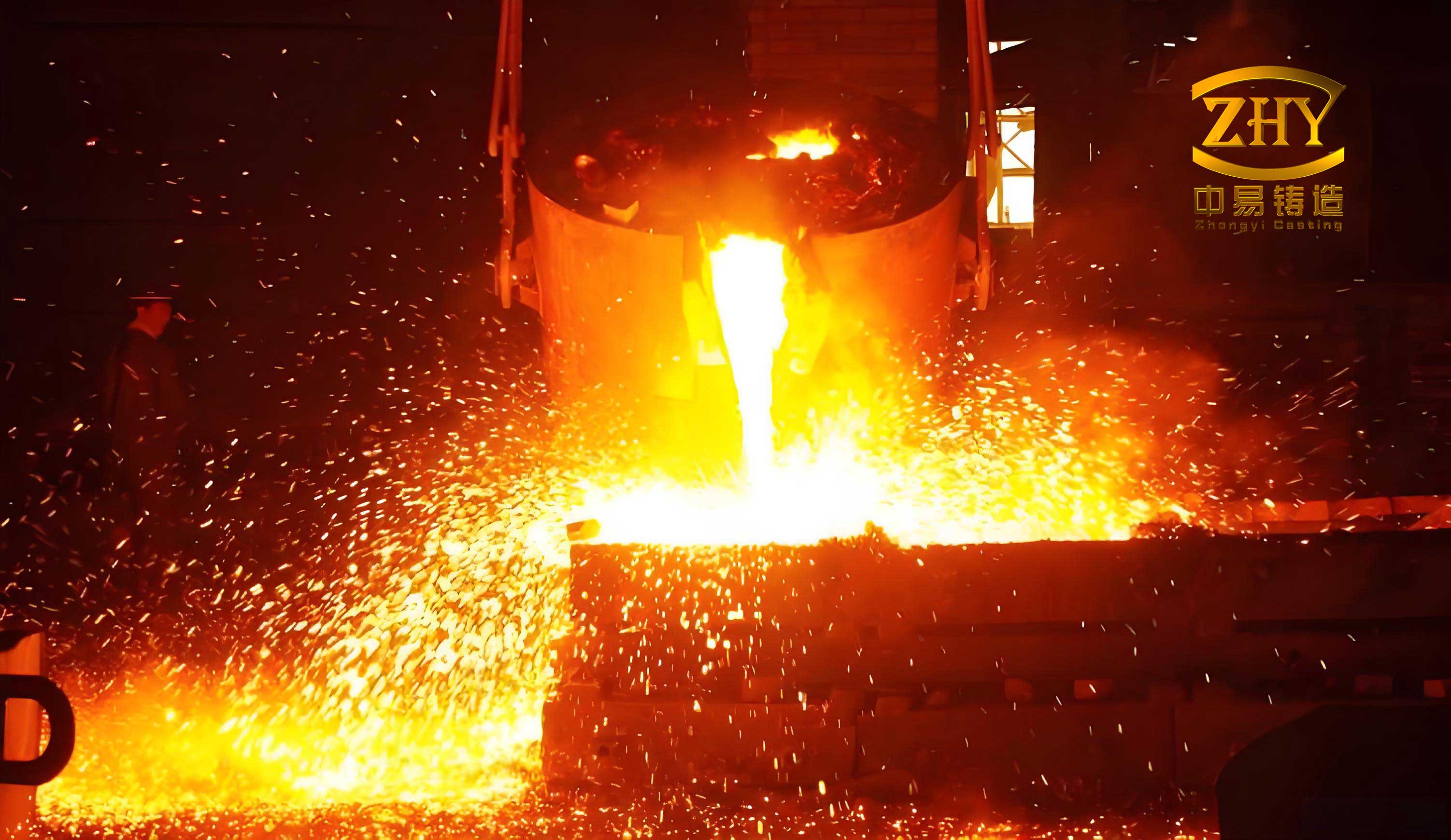
The melting and pouring operations were conducted with three ladles to manage the large volume of ductile cast iron. Pouring temperature was maintained at 1,330–1,350°C to ensure fluidity while minimizing gas absorption. We employed a fast, continuous pouring practice without interruption. Prior to pouring, four 10-ton weights were placed on the mold, supported by steel pipes to counter metallostatic forces.
After pouring, the ductile cast iron casting was allowed to cool slowly in the mold for 240 hours to facilitate stress relief annealing, leveraging the insulating properties of resin sand. The shakeout temperature was kept below 300°C to avoid thermal cracking. The risers were removed, and the casting was inspected for defects.
To evaluate the quality of the ductile cast iron pump body, we performed mechanical tests and metallographic analysis on attached test lugs. The results, summarized in the table below, meet the QT500-7 specifications:
| Sample | Tensile Strength (MPa) | Yield Strength (MPa) | Elongation (%) | Hardness (HB) | Graphite Nodule Diameter (μm) | Nodularity (%) | Pearlite (%) |
|---|---|---|---|---|---|---|---|
| 1 | 460 | 325 | 11.0 | 175 | 49.2 | 92.06 | 54.91 |
| 2 | 490 | 330 | 7.0 | 177 | 44.5 | 92.00 | 60.71 |
| 3 | 485 | 330 | 7.5 | 179 | 52.1 | 90.54 | 57.89 |
The microstructure exhibited well-formed graphite nodules in a matrix of ferrite and pearlite, confirming effective spheroidization. The nodularity exceeded 90%, which is excellent for ductile cast iron. The solidification time \( t_s \) can be estimated using the Chvorinov’s rule:
$$ t_s = k \cdot M^n $$
where \( k \) is a mold constant, and \( n \approx 2 \) for sand molds. With chills, we achieved \( t_s < 50 \, \text{min} \), preventing graphite flotation and shrinkage.
In conclusion, through systematic process design and control, we successfully produced a high-integrity ductile cast iron pump body for sand suction applications. Key achievements include the integration of EPS mold patterns with resin sand, optimized gating and risering, and rigorous metallurgical treatments. The use of chills and controlled cooling minimized defects, while multiple inoculation steps ensured superior nodularity. This project underscores the viability of ductile cast iron for large, complex castings and provides a reference for similar heavy-section components. Future work could explore computational simulations to further refine the chilling layout and reduce trial cycles. Overall, the ductile cast iron material has proven its robustness under demanding conditions, and our process innovations have enhanced its manufacturability.