
As a widely utilized manufacturing method, sand casting offers significant advantages in producing complex, near-net-shape metal components, particularly for low to medium volume production runs. The inherent flexibility of the mold-making process allows for the fabrication of parts with intricate geometries that might be challenging or costly to achieve through other means. This study delves into a detailed investigation into the sand casting process tailored for a specific category of components: semi-enclosed aluminum-copper (Al-Cu) alloy shells. These sand casting parts are characterized by their demanding structural requirements, necessitating high integrity, precise dimensions, and superior mechanical properties. The objective is to establish a robust and reliable manufacturing protocol that ensures consistent quality for such critical sand casting parts.
The selection of Al-Cu alloys, notably from the 2xxx series, is strategic due to their exceptional combination of high specific strength, good fatigue resistance, and excellent machinability in the heat-treated condition. These attributes make them indispensable for advanced applications in aerospace, defense, and high-performance automotive sectors. However, their casting, especially for thin-walled and structurally complex sand casting parts like semi-enclosed shells, presents distinct challenges. These include the tendency for hot tearing due to a long freezing range, the formation of microporosity, and the need for precise control over solidification to achieve sound microstructure and mechanical properties. Therefore, a meticulously designed sand casting process is paramount.
Component Analysis and Technical Specifications
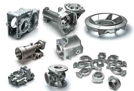
The target component is a semi-enclosed shell structure. Its primary geometrical and functional characteristics impose specific constraints on the casting process. A thorough analysis is the foundation of any successful casting design.
Geometrical Characteristics:
- The component features a dominant semi-enclosed form with one end open.
- Wall sections are relatively uniform but transition into localized thicker regions, such as mounting flanges or stiffening ribs.
- Internal surfaces often have complex contours and may be designated as non-machined, placing a premium on as-cast surface finish and dimensional accuracy.
- The overall envelope dimensions can be substantial, influencing mold handling and pouring methodology.
Technical Requirements: The performance demands for these sand casting parts are stringent and are typically outlined in relevant industrial or proprietary standards. Key specifications include:
| Requirement Category | Specification | Standard/Reference |
|---|---|---|
| Internal Soundness | Freedom from shrinkage cavities, porosity, cracks, and non-metallic inclusions above a specified level. | Class I per HB 963-2005 (or equivalent ASTM, MIL standards) |
| Mechanical Properties | Tensile Strength (Rm) ≥ 320 MPa, Yield Strength (Rp0.2) ≥ 230 MPa, Elongation (A) ≥ 3% (in T6 temper). | Material specification (e.g., A206.0, 201.0) |
| Dimensional Accuracy | General dimensional tolerances conforming to CT9 level as per ISO 8062 / GB-T 6414. | Casting Tolerance Standard |
| Surface Integrity | No surface defects like cold shuts, sand inclusion, or excessive roughness on designated non-machined areas. | Visual and penetrant testing criteria |
| Repair Restrictions | Welding or major rectification may be prohibited for critical high-integrity applications. | Product engineering specification |
Process Design Philosophy for High-Integrity Sand Casting Parts
The process design for these semi-enclosed sand casting parts revolves around three core principles: controlled filling, directional solidification, and minimized thermal distortion.
1. Gating and Pouring System Design: For tall, semi-enclosed geometries, a bottom-gating system is almost always mandatory to ensure tranquil mold filling. A vertical slot (or step) gate system connected to a central downsprue is highly effective.
- Rationale: Bottom filling reduces metal turbulence, minimizes air entrapment and oxide film formation, and allows for a steady temperature gradient to be established from the top (last to fill) towards the bottom gates.
- Design Calculations: The number of vertical feeding gates (n) can be initially estimated based on the part’s perimeter (S) and nominal wall thickness (δ):
$$ n = k \cdot \frac{S}{\delta} $$
where \( k \) is an empirical coefficient typically between 0.016 and 0.028, adjusted for alloy characteristics and pouring method. The slot dimensions (thickness \(a\), width \(b\)) and sprue diameter (D) are interrelated:
$$ a \approx (0.8 \text{ to } 1.5) \delta $$
$$ D \approx (4 \text{ to } 6) a $$
$$ b \approx \frac{D}{2} + (15 \text{ to } 35) \text{ mm} $$
These gates serve the dual purpose of metal delivery and feeding channels during solidification.
2. Solidification Control: Use of Chills and Risers: Achieving soundness in sections of varying thickness is critical.
- Chills: Metallic chills (typically iron or copper) are strategically placed adjacent to thick sections or at the extremities of the casting farthest from the gates. Their function is to rapidly extract heat, creating a steep thermal gradient and enforcing a solidification front that moves from the chilled area back towards the feeder gates. This can be modeled using the Chvorinov’s Rule for solidification time (t) of a section:
$$ t = C \left( \frac{V}{A} \right)^n $$
where \(V\) is volume, \(A\) is surface area, \(C\) is a mold constant, and \(n\) is an exponent (~2). Chills effectively increase the local \(A\), drastically reducing \(t\) and promoting directional solidification. - Risers (Feeders): Insulated or exothermic risers are placed on the thickest sections, such as top flanges or heavy bosses, which are the last to solidify. Their design ensures they remain molten longest, supplying liquid metal to compensate for the volumetric shrinkage of the casting. The required riser volume \(V_r\) must satisfy:
$$ V_r \geq \frac{\beta \cdot V_c}{\eta – \beta} $$
where \(V_c\) is the volume of the casting region fed, \(\beta\) is the volumetric shrinkage coefficient of the alloy (~0.06 for Al-Cu), and \(\eta\) is the feeding efficiency of the riser.
3. Pouring Methodology – Counter-Pressure/Differential Pressure Casting: Employing a differential pressure (or low-pressure) casting process for producing these sand casting parts offers distinct advantages over conventional gravity pouring.
- Process: The furnace holding molten metal is sealed and subjected to a controlled gas pressure (air or inert gas). This pressure forces the metal up a refractory tube (stalk) into the mold cavity, which is under atmospheric or a slightly different pressure.
- Benefits for Sand Casting Parts:
- Controlled Fill: Velocity and fill profile are governed by applied pressure, leading to laminar, non-turbulent filling.
- Enhanced Feeding: The pressure is maintained during solidification, effectively increasing the metallostatic head and improving feeding efficiency, thereby reducing microporosity.
- Improved Mechanical Properties: The combination of clean filling and pressure-assisted feeding results in denser castings with superior and more reproducible mechanical properties.
Numerical Simulation for Process Optimization
Prior to physical trials, numerical simulation of the casting process is indispensable. Using software like NovaFlow&Solid, MAGMASOFT, or ProCAST, the entire process from mold filling to solidification and cooling can be virtually analyzed.
Simulation Workflow:
- Geometry Preparation & Meshing: The 3D CAD models of the part, gating system, chills, and risers are imported. The assembly is discretized into a finite volume/difference mesh. A finer mesh is applied to critical areas like thin walls and gate regions.
- Material Property Assignment: Thermo-physical properties of the Al-Cu alloy (density, thermal conductivity, specific heat, latent heat, fraction solid curve) and the sand mold (permeability, strength, thermal properties) are assigned.
- Boundary Condition Definition: Pouring temperature, filling sequence (for gravity) or pressure curve (for counter-pressure), and interfacial heat transfer coefficients (IHTC) between metal/mold and metal/chill are defined.
$$ \text{IHTC} = \frac{q}{\Delta T} $$
where \(q\) is heat flux and \(\Delta T\) is the temperature difference at the interface. - Analysis and Results Interpretation: The simulation predicts:
- Fill Pattern: Visualizes potential areas of mistuning, air entrapment, or cold shuts.
- Thermal Fields & Solidification Sequence: Identifies last-to-freeze zones (potential shrinkage areas) and validates the effectiveness of chills and risers.
- Defect Prediction: Uses criteria functions (e.g., Niyama criterion for shrinkage porosity) to highlight regions susceptible to defects.
$$ G / \sqrt{R} \leq \text{Critical Value} $$
where \(G\) is temperature gradient and \(R\) is cooling rate.
Outcome: The simulation allows for iterative optimization of gate sizes, chill placement, and riser design virtually, saving substantial time and cost before committing to tooling. It provides a high-confidence prediction that the designed process will yield sound sand casting parts.
Mold Design and Manufacturing for Precision Sand Casting Parts
The pattern equipment used to produce the sand molds must account for all factors influencing the final part dimensions and quality.
Pattern Design Considerations:
| Factor | Consideration | Typical Value/Rule |
|---|---|---|
| Shrinkage Allowance | Pattern is made oversized to compensate for metal contraction upon cooling. | ~1.3% to 1.6% for Al-Cu alloys, varies with section size. |
| Machining Allowance | Extra material added on surfaces to be machined post-casting. | 3-6 mm depending on part size and casting tolerance. |
| Taper on vertical faces to allow pattern removal from sand without damage. | 1° to 3° for external surfaces; slightly more for internal cores. | |
| Fillets and Radii | Replacing sharp corners with radii to reduce stress concentration and improve metal flow. | Minimum R3-R5 mm for non-stressed areas; larger for high-stress junctions. |
| Core Design | For internal cavities of the semi-enclosed shell. Must consider core prints for support, venting, and ease of removal. | Core boxes are precision-machined from metal (e.g., cast iron, aluminum). |
Mold Manufacturing: The patterns are typically machined from high-grade cast iron or aluminum. For high-volume production of such sand casting parts, metal (iron) molds are used to produce the sand molds themselves via a molding machine, ensuring high dimensional repeatability and mold surface finish. This involves creating a cope and drag pattern plate assembly.
Foundry Operations: From Sand to Casting
1. Sand Mold and Core Production: Chemically bonded sands (e.g., phenolic urethane cold-box, silicate-ester) are commonly used for their high strength, dimensional stability, and good collapsibility.
- Process: Sand mixed with binders and catalysts is blown into core boxes or around pattern plates. The chemical reaction cures the sand at room temperature, forming rigid molds/cores.
- Drying & Coating: Molds/cores may be dried in low-temperature ovens (~200°C) to remove moisture and enhance strength. A refractory coating (e.g., zircon-based wash) is applied to the mold cavity surface to improve surface finish of the sand casting parts and prevent metal penetration.
2. Melting and Metal Treatment:
- Charge Materials: High-purity primary aluminum, copper master alloys, and pre-alloyed ingots are used.
- Furnace: Melting is conducted in electric resistance or induction furnaces under a protective flux cover to minimize oxidation and hydrogen pickup.
- Degassing & Grain Refinement: Prior to pouring, the melt is treated. Rotary degassing with inert gas (Argon) is performed to reduce dissolved hydrogen below a critical level to prevent gas porosity. Grain refiners (e.g., Al-Ti-B rods) are added to promote a fine, equiaxed grain structure, enhancing mechanical properties and castability.
3. Pouring and Solidification: The prepared sand mold is assembled, secured, and placed on the differential pressure casting equipment. The controlled pressure cycle is executed:
- Pressurization: The furnace chamber is pressurized, forcing metal up the transfer tube into the mold.
- Filling & Pressure Hold: Pressure is maintained to ensure complete fill and then held during the initial solidification phase to aid feeding.
- Depressurization & Cooling: Pressure is released, and the casting solidifies fully in the mold.
Quality Assessment and Results for the Sand Casting Parts
A comprehensive validation protocol is applied to the cast components to verify they meet all specified requirements.
1. Dimensional Inspection: Using Coordinate Measuring Machines (CMM) or laser scanning, the casting is measured against its nominal CAD model. The analysis confirms that the vast majority of dimensions fall within the CT9 tolerance band, validating the pattern design and process stability for these sand casting parts. Deviations are analyzed for root causes (e.g., uneven mold restraint, core shift).
2. Non-Destructive Testing (NDT):
- Radiographic Testing (X-ray): Inspects the internal structure for shrinkage, porosity, and inclusions. Acceptance is based on reference radiographs per relevant standards (e.g., ASTM E155).
- Liquid Penetrant Testing (PT): Applied to all critical surfaces to reveal surface-breaking defects like cracks or cold shuts.
Results indicate internal soundness equivalent to Class I requirements and no rejectable surface defects.
3. Mechanical Property Verification: Separate test bars cast from the same melt (keel blocks or separately cast coupons) are heat-treated (T6: Solution Heat Treatment, Quenching, and Artificial Aging) alongside the castings and tested. Results consistently exceed the minimum specifications.
| Sample # | Ultimate Tensile Strength (MPa) | Yield Strength (MPa) | Elongation (%) |
|---|---|---|---|
| 1 | 341 | 248 | 4.2 |
| 2 | 335 | 242 | 3.8 |
| 3 | 338 | 245 | 4.0 |
| Specification Min. | 320 | 230 | 3.0 |
4. Microstructural Analysis: Metallographic examination of sections from the casting reveals a fine-grained microstructure with uniformly distributed secondary phases (e.g., Al₂Cu), absence of coarse intermetallics or deleterious phases, and minimal porosity, confirming the effectiveness of the melt treatment and solidification control.
Conclusion and Outlook
This comprehensive study demonstrates a viable and robust manufacturing route for producing high-integrity, semi-enclosed Al-Cu alloy components via sand casting. The synergistic integration of advanced process design principles—featuring a bottom-fed gating system, strategic use of chills and risers, and the application of differential pressure casting—has proven successful. This methodology ensures controlled filling, promotes directional solidification, and enhances feeding, directly addressing the key challenges associated with casting high-strength aluminum alloys.
The validation through numerical simulation prior to tooling commitment, followed by rigorous quality control using dimensional metrology, NDT, and mechanical testing, confirms that the resulting sand casting parts meet stringent aerospace-grade requirements for internal soundness, mechanical performance, and dimensional accuracy (CT9).
Future work may focus on further optimizing the process for even thinner-walled sand casting parts, integrating real-time process monitoring sensors, and exploring the use of advanced binder systems for improved environmental sustainability and casting surface quality. The established framework provides a solid foundation for the reliable production of complex, high-performance aluminum alloy castings where cost-effectiveness for medium volumes and design flexibility are critical.