
Producing high-quality machine tool castings is a fundamental pillar for manufacturing durable, precise, and aesthetically pleasing machine tools, especially for the competitive export market. The surface quality of a machine tool casting is not merely a cosmetic concern; it is a direct indicator of the integrity of the manufacturing process and significantly impacts subsequent machining, assembly, and the final product’s performance and value. Our experience in supplying castings for export-oriented machine tools like bench lathes and drilling machines has underscored that achieving superior surface finish is a systematic endeavor. It requires a holistic approach encompassing the establishment of stringent standards, meticulous process design, advanced material application, and rigorous control over every production stage. This article details our comprehensive methodology for elevating the surface quality of machine tool castings, leveraging first-hand insights and proven techniques.
1. Defining and Measuring Surface Quality for Machine Tool Castings
The first critical step in improving machine tool casting quality is to define precisely what constitutes “surface quality.” Moving beyond generic standards, we have established a multi-faceted set of internal specifications that are stricter than general national casting standards. For a machine tool casting, surface quality is quantified through several key, measurable indicators. These parameters are summarized in the table below, forming the cornerstone of our quality control system.
| Quality Indicator | Definition & Scope | Typical Target for Export Machine Tool Castings |
|---|---|---|
| Dimensional Accuracy | Deviation of overall casting dimensions, wall thickness, and rib thickness from specified drawing values. Critical for machined surfaces, planes, and bore locations. | Tighter than Grade CT10 per ISO 8062. Critical mating surfaces held to ±0.5mm. |
| Surface Irregularities | Presence of visual defects like flash, veining, sand expansion scabs, flow marks, shrinkage cavities, and unwanted projections on non-machined surfaces. | No flash > 0.5mm. No visible scabs, veining, or shrinkage on exterior surfaces. |
| Surface Cleanliness | Degree of surface contamination by adhered sand, burn-on, residual core sand, coating deposits, or rust. Expressed as the percentage of uncontaminated surface area. | > 98% uncontaminated surface area for visible exterior surfaces. |
| Flatness Deviation | Distortion or warping of large flat planes, such as mounting beds or tables, crucial for machine assembly. | < 0.5mm per 300mm length for key mounting surfaces. |
| Surface Roughness (Non-machined) | The micro-scale texture of the as-cast surface, measured as Ra (Arithmetical Mean Deviation). | Ra ≤ 25 μm (typical), with key areas targeted for Ra ≤ 12.5 μm. |
| Profile Definition/Sharpness | Clarity and sharpness of structural features like bosses, windows, louvers, and identification marks. | Full, sharp reproduction of pattern detail. No rounding greater than R1.5mm. |
To enforce these standards, a combination of inspection methods is employed systematically:
- Layout Inspection on Surface Plates: Used for first-article inspection of new patterns or critical castings to verify comprehensive dimensional accuracy against CAD data.
- Comparative Method with Gauges & Templates: Custom gauges for critical wall thicknesses and profile templates for complex contours enable rapid production-line checks.
- Straightedge and Feeler Gauge Inspection: For assessing flatness deviation on large plane surfaces.
- Visual Inspection under Controlled Lighting: The primary method for assessing surface irregularities, cleanliness, and profile sharpness, conducted by trained inspectors.
- Roughness Comparison Samples: Physical Ra sample plates are used for tactile and visual comparison to determine non-machined surface roughness.
The relative cleanliness of a surface can be quantified using a simple formula for audit purposes. If At is the total surface area of the casting and Ad is the total area affected by defects (sand adhesion, scale, etc.), then the Clean Surface Area Percentage (CSAP) is given by:
$$ \text{CSAP} = \left(1 – \frac{A_d}{A_t}\right) \times 100\% $$
Our target is to maintain CSAP > 98% for all external surfaces of an export-grade machine tool casting.
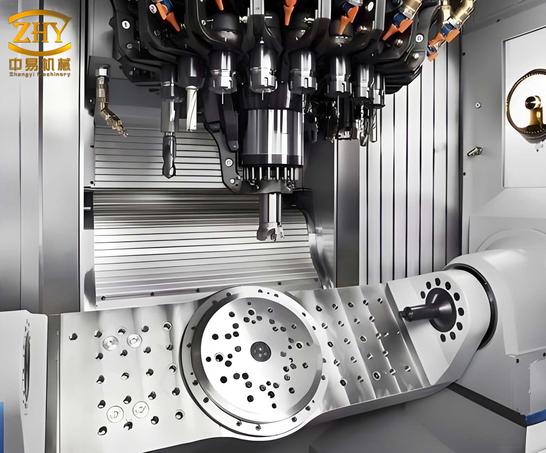
2. Foundry Process and Tooling Design for Superior Machine Tool Castings
The foundation for a high-quality machine tool casting is laid during the process and tooling design phase. Strategic decisions here have a profound impact on dimensional stability and surface finish.
2.1. Strategic Parting Line Selection and Core Design
The primary goal is to minimize complexity. We prioritize designs that use the fewest possible parting lines to reduce the surface area prone to flash formation. Furthermore, maximizing the integrity of core assemblies is crucial. By designing single, complex cores to replace multiple smaller ones, we drastically reduce the number of core joints. This minimizes the risk of fin formation at joints and improves the internal surface finish and dimensional accuracy of cored cavities. The guiding principle is: fewer parting lines and core joints directly translate to better surface finish and contour definition for the machine tool casting.
2.2. Precision in Pattern Allowances
The selection of pattern allowances is a precise science, not a rule-of-thumb exercise. For machine tool castings requiring high dimensional accuracy, we apply the following rigorous approach:
- Draft Angles: Kept to the absolute minimum required for pattern extraction, typically using the “add-to-thickness” or “add-to-dimension” method to preserve critical part geometry.
- Shrinkage Allowance: This is not a universal value. We conduct pattern trials for new or complex geometries. It is common to apply different shrinkage rates along different axes due to constraints from the mold and cores. For instance, a lathe bed casting might require:
$$ \text{Length Shrinkage} = 0.8\%,\quad \text{Width Shrinkage} = 1.0\%,\quad \text{Height Shrinkage} = 0.7\% $$
This anisotropic approach compensates for differential restraint during solidification. - Parting Line Negative Allowance: Carefully calculated to compensate for mold wall movement and ensure precise dimensional alignment across the parting line.
2.3. Advanced Foundry Techniques
We actively integrate modern casting research into production. Two pivotal theories applied to our machine tool castings are:
- Eutectic Expansion Feeding (Equilibrium Solidification): This principle guides the design of feeding systems for gray iron castings. It leverages the graphitic expansion phase during eutectic solidification to achieve internal soundness with minimal feeder size and placement, reducing surface sinks and distortion.
$$ V_{\text{feed}} \propto \frac{M_c \cdot \Delta T}{t_{\text{solid}} } $$
Where $V_{\text{feed}}$ is the required feed volume, $M_c$ is the casting modulus, $\Delta T$ is the solidification temperature range, and $t_{\text{solid}}$ is the local solidification time. This allows for optimized riser design. - Large Orifice Pouring Theory: We design gating systems with relatively large, non-turbulent sprue and runner cross-sections to ensure a smooth, non-aspirating flow of metal. This minimizes oxide formation and slag entrainment, which are primary causes of surface and subsurface defects in the final machine tool casting.
2.4. Flexible and Durable Tooling Strategy
Given the medium-to-low volume, high-mix nature of machine tool casting production, we employ a hybrid tooling strategy that balances durability, precision, and cost-effectiveness.
| Tooling Type | Construction | Application & Benefit for Machine Tool Castings |
|---|---|---|
| Composite Master Patterns (for Molds) | Steel plate shell structure filled with stabilized hardwood. Uses modular standard and custom steel plates with bolt-together assembly. | Provides near-metal pattern durability and dimensional stability at ~40% of the cost of a full metal pattern. Ideal for large or long-running parts like gearbox housings or column bases. |
| Modular Core Boxes | Standardized aluminum or steel frame (cope and drag) with interchangeable, precision-machined inserts made from aluminum, hardwood, or plastic that define the core cavity. | Dramatically reduces cost and lead time for core tooling. Allows rapid design changes. Excellent for producing complex, high-tolerance cores for machine tool casting internal passages. |
| Metal/Resin Patterns on Match Plates | Cast aluminum or high-density polyurethane patterns mounted on precision machined match plates. | Used for high-volume, smaller castings (e.g., brackets, handles). Ensures excellent dimensional repeatability and surface finish from the mold. |
3. Molding Materials and Coating Systems for Machine Tool Castings
The interaction between molten iron and the mold/core surface is the crucible where surface quality is determined. Selecting and controlling molding materials and coatings is therefore paramount.
3.1. Molding Sand Systems
We use different sand systems optimized for the size and section of the machine tool casting.
| Casting Type | Mold Type | Sand System Specification | Purpose & Quality Impact |
|---|---|---|---|
| Small Castings (< 50 kg) | Green Sand | Fine silica sand (AFS GFN 70-90). Low bentonite (<8%). Premium coal dust/seacoal blend. Controlled moisture (2.8-3.5%). | Provides excellent surface finish detail, minimizes veining and gas defects on smaller, intricate machine tool castings. |
| Medium-Large Castings (50 – 2000 kg) | Skin-Dried Clay Sand | Coarse silica sand (AFS GFN 50-70). High-quality bentonite. Dried mold surface to a depth of 5-10mm. | Provides high mold strength and thermal stability to resist metal pressure and expansion, preventing mold wall movement and scabbing on large machine tool castings like beds and frames. |
| Cores (All Sizes) | Furan No-Bake Resin Sand | Silica sand, furan resin (0.9-1.4%), sulfonic acid catalyst. High core strength, excellent collapsibility. | Produces cores with exceptional surface finish, dimensional accuracy, and easy shakeout. Critical for achieving clean internal cavities in complex machine tool castings. |
3.2. Refractory Coating (Wash) Technology
A high-quality refractory coating is the final barrier that defines the as-cast surface roughness of the machine tool casting. Our proprietary coating formulation and application process are key differentiators.
Coating Composition:
- High-Purity Amorphous Graphite (screened -200 mesh): 40%
- Flake Graphite (screened -100 mesh): 40%
- Activated Bentonite: 10%
- Sodium Carboxymethyl Cellulose (CMC) Binder: 1%
- Water: Balance (added during slurry preparation)
Mixing and Application Protocol: The dry ingredients are mixed in a high-shear mixer for 15 minutes. Pre-hydrated bentonite slurry is added, and the mixture is mulled for 2-3 hours to achieve a smooth, stable paste for storage. For application, the paste is diluted with water to precise specific gravities:
$$ \text{First Coat Slurry Density} = 1.45 \text{ g/cm}^3 \quad \text{(for excellent penetration and base layer)} $$
$$ \text{Second Coat Slurry Density} = 1.35 \text{ g/cm}^3 \quad \text{(for a smooth, sealing top layer)} $$
Cores are predominantly dipped for uniform, controllable coating thickness. Molds are brushed or sprayed. The double-coating system ensures a flawless refractory barrier, directly yielding a smoother machine tool casting surface with Ra values often below 25 μm and virtually eliminating burn-on and metal penetration defects.
4. Melting, Pouring, and Solidification Control
The quality of the liquid metal and how it is introduced into the mold are critical final steps. Poor metal quality or turbulent pouring can ruin the work invested in perfect molds and cores.
4.1. Melting and Metal Treatment
We operate a modern, instrumented cupola furnace paired with a holding/receiving furnace (induction or channel type). The focus is on achieving high-temperature, low-oxidation iron.
$$ \text{Target Pouring Temperature Range} = 1380^\circ\text{C} – 1420^\circ\text{C} $$
Key parameters monitored and controlled include:
| Parameter | Target Range | Impact on Machine Tool Casting Surface |
|---|---|---|
| Coke Ratio | 1:8 to 1:10 | Controls melting rate and superheat. Insufficient superheat leads to mistruns and poor surface finish. |
| Blast Rate & Temperature | Optimized for stable, oxidizing-reducing balance | Minimizes FeO slag formation, which causes pitting and slag inclusions on the casting surface. |
| Final Molten Metal Chemistry | Low S (<0.1%), controlled Mn/S ratio | Promotes healthy graphite formation, improves fluidity, and reduces the risk of subsurface pinholes and shrinkage. |
Furthermore, we employ ceramic foam filters (e.g., 10 ppi) in the gating system to trap non-metallic inclusions, resulting in cleaner metal entering the mold cavity and a cleaner surface on the machine tool casting.
4.2. Pouring and Solidification Philosophy
Our guiding principle is: “Pour hot, but not too hot, and let it solidify quietly.” More formally:
- High Superheat in Furnace: Achieve temperature well above the liquidus to ensure complete dissolution of carbides and gases.
- Quiet Holding/Pouring: Use the holding furnace to allow gases to rise and slag to separate. Pour from a minimal height with a pressurized, non-turbulent gating system.
- Lower Pouring Temperature: Aim for the lower end of the target range (e.g., 1380°C) for the specific casting section size. This reduces the total heat input into the mold, minimizing sand-metal interaction (burn-on), surface grain coarsening, and overall mold dilation which can cause veining.
The solidification progression is managed through strategic chilling and risering based on modulus calculations to ensure directional solidification towards the feeders, preventing surface shrinkage on the critical sections of the machine tool casting.
5. Casting Cleaning and Finishing: The Final “Cosmetic” Stage
Cleaning is not merely about removing sand; it is a precision finishing process for the machine tool casting. A systematic multi-stage approach is essential.
| Casting Size | Stage 1: Rough Cleaning | Stage 2: Precision Cleaning | Stage 3: Final Finishing |
|---|---|---|---|
| Small (< 50 kg) | Tumbling in a hexagonal barrel mill with star-shaped abrasives. | Shot blasting in a rotary table blast cabinet using fine steel shot (S330). | Hand-grinding with pedestal grinders and pneumatic die grinders fitted with flap discs for flash removal and blending. Immediate application of rust-preventative primer. |
| Medium-Large (> 50 kg) | Vibration shakeout to remove bulk sand, followed by removal of core sand. | Shot blasting in a continuous through-type or rotary-hook blast room. Adjustable blast parameters for different surfaces. | Extensive use of portable pneumatic grinders, belt sanders, and specialized deburring tools. All non-machined surfaces are meticulously inspected and finished. Final primer coat applied. |
This rigorous cleaning protocol ensures that every machine tool casting meets the stringent surface cleanliness and profile sharpness standards before it leaves the foundry floor. The application of a protective primer is a mandatory final step to preserve the achieved surface quality during storage and transport, ensuring the customer receives a casting that is ready for machining and reflects the high standards of the final machine tool product.
In conclusion, elevating the surface quality of machine tool castings for demanding export markets is a comprehensive, integrated effort. It begins with a clear definition of quality metrics and permeates every single step of the foundry process: from intelligent tooling design and precision patternmaking, through the selection and control of advanced molding materials and coatings, to the disciplined management of molten metal quality and pouring practices, and culminates in a meticulous cleaning and finishing regimen. There is no single “magic bullet.” Success is built on the consistent and synergistic application of these principles, turning the production of a high-surface-quality machine tool casting from an art into a controlled, repeatable science. This holistic approach is indispensable for foundries aiming to compete and excel in the global market for precision machine tools.