
In my extensive experience within the foundry industry, the integration of rapid prototyping technologies, particularly Selective Laser Sintering (SLS), has fundamentally transformed the approach to manufacturing complex sand casting parts. This article delves into the detailed process, advantages, and applications of resin sand mold rapid casting based on SLS technology, drawing from firsthand implementation and analysis. The ability to bypass traditional pattern-making stages offers unprecedented speed and flexibility, especially for prototypes and low-volume production runs of intricate sand casting parts.
The core of this methodology lies in using SLS to directly fabricate sand molds from a CAD model. The traditional sand casting process involves creating a pattern, which is a replica of the final part, used to form the mold cavity in sand. For complex geometries, especially those with internal passages, this can be extremely time-consuming and costly. SLS rapid prototyping eliminates this bottleneck. The process begins with a 3D CAD model of the desired sand casting part. This model is then used to create a digital mold assembly, which is sliced into thin layers for the SLS machine. The machine utilizes a laser to selectively sinter layers of resin-coated sand, building the mold layer by layer. The un-sintered sand remains loose, acting as support, and is removed after the build. The resulting sand mold often requires a secondary thermal post-curing cycle to achieve full strength comparable to conventionally produced shell molds or core assemblies.
The fundamental thermal process during laser sintering can be modeled. The energy input from the laser must be sufficient to melt the resin binder and fuse the sand particles. A simplified energy balance for a single sintered layer can be expressed as:
$$ E_l = \rho_s \cdot c_s \cdot \Delta T \cdot V_s + H_f \cdot m_r $$
Where \( E_l \) is the laser energy delivered, \( \rho_s \) is the density of the sand mix, \( c_s \) is its specific heat capacity, \( \Delta T \) is the temperature rise required, \( V_s \) is the volume of sand sintered, \( H_f \) is the latent heat of fusion for the binder resin, and \( m_r \) is the mass of resin fused. This equation highlights the critical parameters governing the quality of the sintered mold for producing durable sand casting parts.
After post-processing, the molds are assembled, gating systems are added if not integrated, and the entire assembly is prepared for pouring. The subsequent steps—melting, pouring, cooling, shakeout, and finishing—are identical to conventional sand casting. The profound difference is the drastic reduction in lead time from design to metal cast part. I have observed lead time reductions of 50% to 80% for complex sand casting parts, which is revolutionary for product development cycles.
To systematically compare traditional sand casting with SLS-based rapid sand casting, the following table summarizes key aspects:
| Aspect | Traditional Sand Casting | SLS-Based Rapid Sand Casting | |
|---|---|---|---|
| Pattern/Mold Tooling | Required (wood, metal, plastic). Long lead time and high cost for complex shapes. | Not required. Mold is built directly from CAD data. | |
| Lead Time for First Article | Weeks to months, depending on pattern complexity. | Days to a week. | |
| Design Flexibility for Sand Casting Parts | Limited by pattern draft and complexity. | Extremely high. Can produce internal cavities, undercuts, and complex geometries without added cost. | |
| Economic Batch Size | High-volume production to amortize tooling cost. | Ideal for single pieces, prototypes, and low-volume batches of sand casting parts. | |
| Material for Mold | Green sand, chemically bonded sand. | Specialty resin-coated sand for SLS. | |
| Dimensional Accuracy | Good, but subject to pattern wear. | High, directly tied to CAD model and machine precision. |
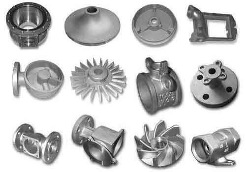
The advantages become particularly evident when dealing with components featuring intricate internal geometries, such as hydraulic manifolds, pump housings, or turbine impellers—all prime examples of demanding sand casting parts. In one application, a complex aluminum housing with multiple intersecting internal oil galleries was required. Using traditional investment casting with wax patterns created via SLS was initially attempted. However, the removal of ceramic shell material from the deep, narrow galleries proved nearly impossible. The shift to direct SLS sand mold casting provided a solution. The mold was designed as a multi-part assembly with integrated cores. The core prints and alignment features were designed into the digital model, ensuring precise assembly. The mold sections were sintered, post-cured, assembled, and poured. The resultant sand casting part required minimal cleaning and successfully met all pressure-tightness specifications.
The mold design phase is critical. Software tools are used to create the negative of the sand casting part, add draft if necessary for mold release (though often minimal is needed), incorporate gating and risering systems, and partition the mold into printable segments. The strength of the sintered sand is a key consideration. The resin binder’s performance can be characterized by its tensile strength development during curing. A common model for cure kinetics is:
$$ \frac{d\alpha}{dt} = k (1-\alpha)^n $$
where \( \alpha \) is the degree of cure, \( t \) is time, \( k \) is a temperature-dependent rate constant following an Arrhenius relationship \( k = A \exp(-E_a/RT) \), and \( n \) is the reaction order. Optimizing the post-cure cycle (time and temperature) based on such models ensures the mold has adequate strength to withstand the metallostatic pressure during pouring, especially for large sand casting parts.
Another significant application is in the manufacture of impellers and rotors. These sand casting parts often have complex, contoured blades that are difficult to mold conventionally. With SLS sand molding, the entire mold cavity—including the intricate passages between blades—can be created as a single core or a combination of cores printed as one monolithic piece. This “one-piece core” approach eliminates core assembly errors and significantly improves the dimensional accuracy of the final sand casting part. For a large-diameter thin-walled impeller, the mold design must account for rapid heat dissipation to avoid mistuns. Preheating the mold before pouring and using thermally insulating riser sleeves might be necessary, aspects easily integrated into the digital mold design.
The economic calculation for adopting this technology is compelling for certain scenarios. The total cost \( C_{total} \) for producing a sand casting part via rapid sand casting can be broken down as:
$$ C_{total} = C_{design} + C_{SLS\_machine\_time} + C_{material\_sand} + C_{post\_processing} + C_{metal\_pour} + C_{finishing} $$
In contrast, traditional costing includes a substantial initial tooling cost \( C_{tooling} \) amortized over the batch size \( N \): \( C_{tooling}/N \). For small \( N \), the rapid method often wins. To illustrate the crossover point, consider the following hypothetical data for a specific complex sand casting part:
| Cost Factor | Traditional Casting (for N parts) | Rapid SLS Sand Casting (per part) |
|---|---|---|
| Tooling/Pattern Cost | $15,000 (one-time) | $0 |
| Mold/Core Production Cost per part | $200 | $800 |
| Other Costs (metal, finishing, etc.) | $300 per part | $300 per part |
| Total Cost for N parts | $15,000 + $500N | $1,100N |
Setting the two equations equal to find the break-even batch size: \( 15,000 + 500N = 1100N \) which solves to \( N = 25 \). This simplified model shows that for batch sizes below 25 units, the rapid method is more economical for this particular sand casting part, ignoring the significant time value of money which further favors rapid prototyping for early market entry.
The material science behind the process is equally fascinating. The sand used is not ordinary foundry sand. It is a precisely engineered mixture of high-purity silica or zircon sand, coated with a thermoplastic phenolic or furan resin. The particle size distribution (PSD) is tightly controlled to ensure good flowability for recoating and high packing density for strength. A typical PSD might follow a modified Andreassen model for optimal packing:
$$ CPFT = \left( \frac{D}{D_{max}} \right)^q \times 100\% $$
Where CPFT is the Cumulative Percent Finer Than, D is the particle diameter, \( D_{max} \) is the maximum particle size, and \( q \) is the distribution coefficient (often near 0.37 for dense packing). A well-packed sand structure leads to better surface finish on the final sand casting part and higher mold strength.
During the sintering process, the laser parameters are crucial. The laser power \( P \), scan speed \( v \), and hatch spacing \( h \) determine the energy density \( E_d \) delivered to the powder bed:
$$ E_d = \frac{P}{v \cdot h \cdot t} $$
where \( t \) is the layer thickness. If \( E_d \) is too low, the binder does not fully melt, leading to weak, porous molds that can cause defects in sand casting parts like penetration or erosion. If \( E_d \) is too high, the resin may degrade or over-cure, causing distortion and poor accuracy. Optimal parameters are determined empirically for each material system.
Post-casting, the properties of the sand casting parts must be evaluated. For aluminum alloys like A356 (similar to ZL101A), mechanical properties can be predicted based on solidification modeling. The local solidification time \( t_f \) within a mold section influences the secondary dendrite arm spacing (SDAS), which correlates with tensile strength \( \sigma_t \):
$$ \lambda_2 = k \cdot t_f^n $$
$$ \sigma_t \approx \sigma_0 – m \cdot \lambda_2 $$
where \( \lambda_2 \) is the SDAS, \( k \) and \( n \) are constants, and \( \sigma_0 \) and \( m \) are material-dependent parameters. Using simulation software during the digital mold design phase allows for the prediction of solidification times and the optimization of riser and chill placement to achieve sound, high-quality sand casting parts.
The versatility of this technology extends beyond aluminum to cast iron, steel, and magnesium alloys. However, the higher pouring temperatures of ferrous alloys pose a greater challenge to the resin-sand mold’s thermal stability. Special high-refractoriness sands and resins with improved burn-out characteristics are employed. The mold may also require additional coatings or washes to prevent metal penetration and improve surface finish on the resulting sand casting parts.
In summary, SLS-based rapid resin sand mold casting is a disruptive technology that offers immense value in agility and cost-effectiveness for producing complex, low-volume sand casting parts. It democratizes access to complex cast geometries, enabling faster innovation cycles across aerospace, automotive, and energy sectors. The direct digital-to-mold pathway eliminates numerous intermediate steps, reduces human error, and provides designers with newfound freedom. As the technology matures, with improvements in build size, speed, and material portfolios, its adoption is set to expand further, solidifying its role as a cornerstone of modern, agile manufacturing for critical sand casting parts.