
(1) After powering up the handheld scanner and connecting it to the computer, use VXelements software to create a scanning item.
(2) Calibrate the scanner according to the instructions and software prompts.
(3) The parameters are configured according to the characteristics of the measured end cover casting. For example, the measured end cover casting is a small cast iron part, so the scanning range is adjusted. The shutter time is kept by default, and the scanning accuracy needs to be adjusted to 0.1mm.
(4) Mark points shall be pasted on the end cover casting. Mark points of different specifications shall not be mixed. The end cover casting is small, and the mark points shall be pasted on the ground as a reference. Therefore, only a single face can be carried out and the end cover casting cannot move during scanning, to ensure the relative position with the mark points remains unchanged. Note that the marker points should not be pasted at the places with large curvature, which will cause errors in the later repair model.
(5) Scan the end cover casting. When scanning, the scanner is 30cm away from the end cover casting, and the prompt light is green to ensure that at least 6 marker points are scanned normally each time. During scanning, the scanning image can be displayed in real-time and free view, and the scanning position can be adjusted. Note that a single laser line can be selected to accurately scan the deep part of the end cover casting during scanning. The scanning process is shown in Figure 1.
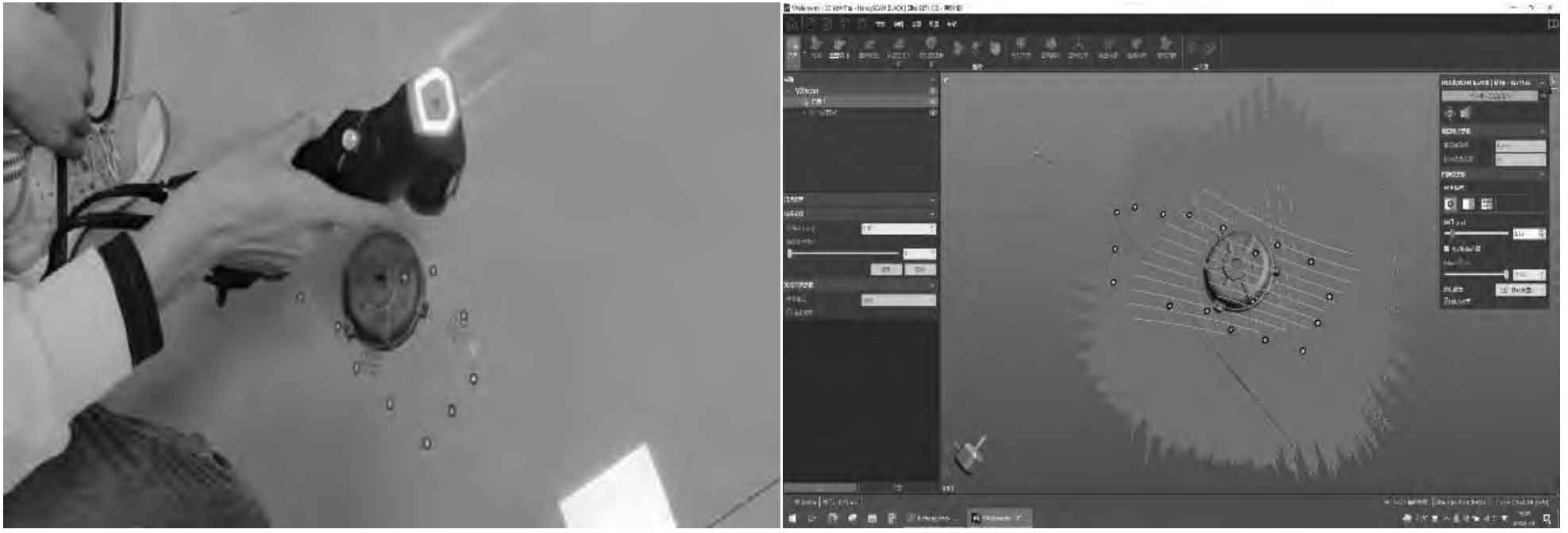
For end cover castings, first scan one face, then create a scan in the same project and scan another face after scanning, and then only need to fit the point cloud files scanned twice to get more accurate feature parameters. VXelements software provides point cloud processing. At the end, check the options of optimizing volume accuracy, filling positioning target, and optimizing boundary accuracy. Use the automatic optimization command of the trained equipment to repair defects such as marker points, and the effect is good.
(6) Process the point cloud file and remove the background from the point cloud file. The background contains a large number of feature points. Without removing the background from the point cloud file, it will waste computer resources and cause the software to open and crash. After the point cloud file is saved, the point cloud will be de-noised, and the extra noise will be removed manually.
(7) The two point cloud files are fitted. There are few common points in the end cover casting scanning. Therefore, the best fitting of the surface in the combined scanning is adopted. The fitting effect is good. The fitting patch is shown in Figure 2.
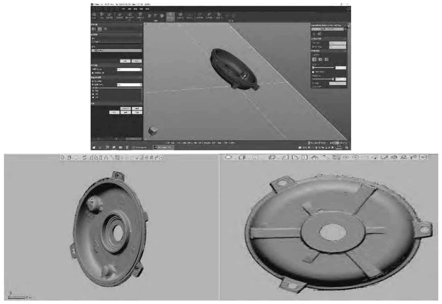
(8) 3D model establishment. Patch the point cloud file with the point cloud processing software. Align the exported patch files, merge them through manual fitting, reduce noise and repair the patch files, delete the redundant patches and isolated patches, and wrap them after sorting out the shape features to get the entities, mesh the entities, and decompose them into patch features. Compare the patch for modeling, adjust the modeling parameters according to the reconstructed solid model, and finally obtain a qualified solid model within the error range through software comparison. Attention should be paid to ensure that the benchmark is correct during modeling. Finally, convert the 3D drawing into the 2D drawing, and draw the end cover casting drawing.
Because the end cap casting is small, the target point is placed on the end cap casting and the ground. When the end cap casting is large, the target point is completely placed on the end cap casting, which can achieve high-precision one-time scanning, eliminating the steps of model building, and achieving the completion of model building in a short time.
After the model is built, the casting process is designed. For single piece and small batch production, only the pouring system and pouring process parameters need to be designed, and the traditional process and tooling design such as sand core need not be carried out. After determining the pouring system, the sand mold shall be designed according to the sand consumption.