
As a basic casting process method in the foundry industry, sand casting is widely used in the manufacturing industry because of its low manufacturing cost, convenient material extraction, simple process and strong operability. However, because of the flexibility of the casting process, how to select and formulate a scientific, reasonable, economical, environmentally friendly and easy-to-implement process plan is still a key issue in actual production practice. The lifting box is mainly involved in the field of petroleum machinery technology. In oil extraction, oil and gas flow from the reservoir layer to the bottom of the well, and from the bottom of the well to the wellhead. Before mining, it is necessary to drive the drill bit through the rotating rod to drill the hole, and then the rotating rod is withdrawn from the hole, and the pump used for pumping oil is inserted from the inlet pipe for mining. The main function of the lifting box is to lift the rotating rod and the subsequent development materials. Because it is the main load-bearing part, it has high requirements for its strength and stability when working. Based on this, this paper analyzes the structural performance and working characteristics of the lifting box, and uses ProCAST software to carry out numerical simulation and comparative analysis, and formulates a set of sand casting process scheme with reasonable process parameters and efficient gating system, so as to guide the production of qualified lifting box castings.
1 Overall analysis of parts
1.1 Structural analysis of parts
The outer contour size of the part is 1 040 mm×760 mm×933 mm, the material is ZG25CrNiMo, the density is 7.85 g/cm3 of the general steel casting, the maximum wall thickness is about 187 mm, the minimum wall thickness is 45 mm, and the three-dimensional model of the part is shown in Figure 1. As shown in Figure 2, the wall thickness of the small end of the part is thicker, and the wall thickness of the large end is uniform without large thermal joints.
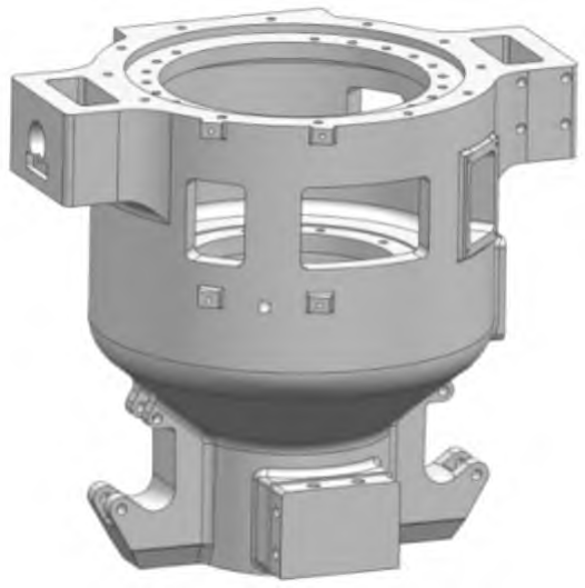
Fig. 1 Three-dimensional drawing of casting
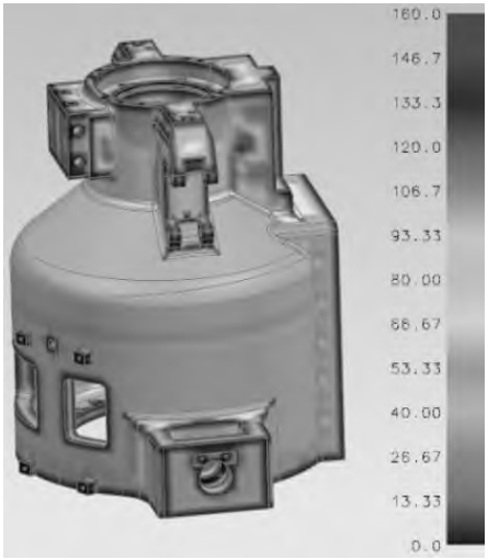
Fig.2. Wall thickness distribution of castings
1.2 Part Material Analysis
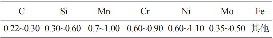
The casting material is low-alloy steel ZG25CrNiMo, which has good toughness properties, high tensile strength, excellent fatigue resistance, its chemical formation The scores are shown in Table 1.
Table1 Chemical composition of the ZG25CrNiMo wB /%
2 Selection of pouring position and parting surface
The selection of pouring position is the same as the parting surface, and the rationality of the parting surface selection is directly related to the quality of the casting. Scheme 1: All castings are placed in the lower type, and the dimensional accuracy is better; Accurate positioning of the lower core of the vertical sand core; Two boxes of horizontal parting, manual modeling is more convenient. However, it is not convenient to start the mold, and it is necessary to add more loose blocks or sand cores (Fig. 3a). Scheme 2 castings are all located in the upper mold, which has the advantages of scheme 1, and only a small amount of loose blocks or sand cores need to be added, and the casting mold is convenient, so scheme 2 (Fig. 3b) is selected.
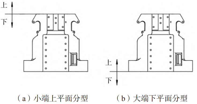
Fig.3. Parting surface scheme
3 Gating system design
3.1 Gating system design scheme
Through the selection of the pouring position and parting surface position scheme 2, the casting pouring system can be used in the bottom injection type and the top injection type. Because the height of the upper mold is more than 1 m, in order to facilitate the modeling, the cross-sprue formed by the ceramic pipe sprue commonly used in steel castings and the wooden mold is used to avoid heat concentration near the sprue. In order to ensure that the temperature of the upper part of the casting is higher and the sequence solidification is more obvious, the top-injection gating system adopts a ceramic tube gating system. According to the weight of the casting, it is poured with a leaky bag (bottom injection type).
3.2 Determination of the cross-sectional area of the two gating systems
When pouring steel castings with a leaky ladle (bottom injection type), choose open casting
Note system. (1) Calculation of bottom-injection gating system. The diameter of the capsule is 50 mm, the ΣA bag = 19.6 cm2, and the ceramic tube sprue is 70 mm. ΣA transverse=39.2 cm2, the cross sprue is bidirectional, and the cross-sectional area is 19.6 cm2. ΣA inner = 43.1 cm2, 6 inner runners were used, and the average cross-section area of each inner runner was 7.2 cm2. The cross-sectional dimensions of the under-injection gating system are shown in Figure 4.
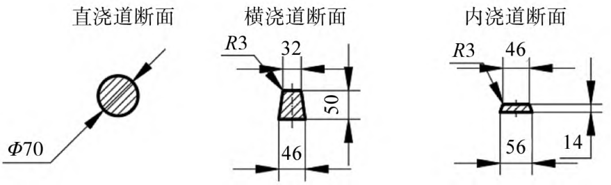
Fig.4. Cross-sectional dimensions of bottom-injection gating system (mm)
(2) Calculation of top-gating system. Cover hole diameter 50 mm,ΣA package = 19.6 cm2, choose 70 mm for ceramic tube sprue. ΣA transverse=39.2 cm2, the cross sprue is bidirectional, and the cross-sectional area is 19.6 cm2, choose to use a ceramic tube with a diameter of 50 mm. Within ΣA = 43.1 cm2
Two sprues were used, with an average cross-sectional area of 21.6 cm2 each, and a ceramic tube with a diameter of 55 mm was selected. The cross-sectional dimensions of the top-injection gating system are shown in Figure 5.
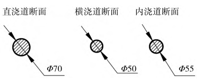
Fig.5. Section size of top-injection gating system (mm)
4 Numerical simulation results and analysis
4.1 Simulation pretreatment
Use NX1847 to create 3D molds of castings, sprue cups, and sprues
type, export the common format and then import it into ProCAST and divide the mesh, square
The total number of meshes of the bottom gating system in case 1 is 1 160 633, and the total number of meshes in the top gating system in scheme 2 is 897 227, and then the simulation is carried out. The pouring temperature was 1 550 °C, the pouring time was 40 s, the sand mold was alkaline phenolic resin sand, the raw sand was silica sand, and the heat exchange coefficient between the metal and the sand was determined to be 500 W/(m2· K)。 Sand core and sand mold are the same material.
4.2 Filling analysis and defect analysis
Filling analysis and defect analysis were carried out on scheme 1 and scheme 2, and the results were obtained
This is shown in Figures 6, 7 and 8. In both schemes, the sprue is in full condition during the pouring process. However, the top-injection gating system in scheme 2 has too much drop during molding, and the molten metal has obvious splashing, which will directly impact the sand core, which is easy to cause sand dropping; The bottom-injection gating system in scheme 1 is filled smoothly and orderly, and the filling effect is obviously better. In terms of time, the filling time of the two schemes was close to 40 s, which met the setting requirements. When the pouring is completed, the upper part of the top-gating gating system in scheme 2 has fewer shrinkage porosity defects, and the lower part is basically the same as scheme 1.
4.3 Selection of gating system
Through numerical simulation analysis, it can be seen that although the upper defects of the casting in scheme 2 are fewer, the lower defects are consistent with scheme 1, especially the filling is unstable and easy to damage the sand core.


Fig.6 Filling analysis of scheme 1


Fig.7 Scheme 2 filling analysis
4.4 Initial Optimization Measures
According to the simulation analysis results, the riser of the casting pouring system was added and shrunk. The lower part of the casting is inconvenient to set the riser because of the structural constraints and the non-machined surface, and the riser can be set up at the upper shrinkage hole part for shrinkage, so the riser is placed in the upper part.
5 Riser design
5.1 Selection of riser type and shape
In order to facilitate the modeling and better shrinkage effect of the riser, this process design uses a heating riser sleeve, which can not be taken out after modeling, and the riser is set as a round open riser. The wall thickness of the upper end of this casting is the largest, and considering the size of the casting structure and the shrinkage distance, the casting only needs a large riser. The modulus method is used to design and calculate the heating and heat preservation riser. A cylindrical heating and insulation riser with a diameter of 300 mm is adopted, and the modulus of the riser height is 5.0 cm when the riser height is 300 mm, which is greater than the calculated value, so the modulus of the selected heating and insulation riser meets the requirements.

Fig.8 Defect analysis of different schemes
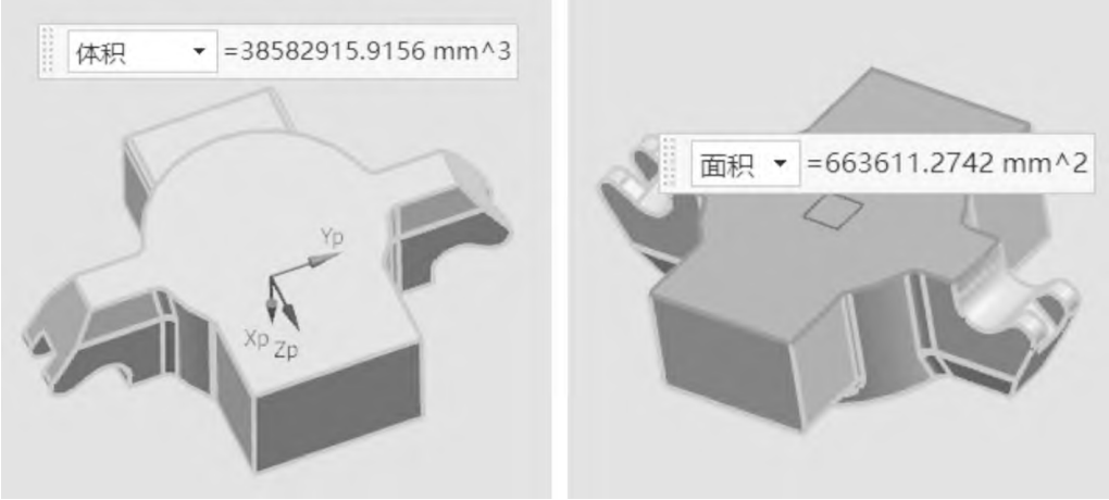
Fig.9 Three-dimensional view of the part to be retracted
5.2 Analysis and summary of the initial optimization results
5.2.1 Simulation pretreatment
The 3D model was imported into ProCAST for simulation analysis, and the model added a heating and insulation riser and a vent hole, the 1# large sand core was a hollow sand core, and the inside was air during the pouring process, and the heating riser sleeve, hollow sand core and lifting lug sand core can be seen in Figure 10.
5.2.2 Solids ratio analysis
Solid-phase ratio analysis of the optimized system using ProCAST from:
As can be seen in Fig. 11a, isolated liquid phase zones appear on both sides of the lower part of the casting due to thicker wall thickness and slower solidification; Fig. 11b: A smaller area of solitary liquid phase is also present in the middle of the casting. The casting is gradually solidified from the bottom to the top, and the riser is finally solidified, and the process design conforms to the principle of sequential solidification; As can be seen from Fig. 11c and d, the cooling of the heating riser is the slowest and the calculation time is long, so as long as the casting is fully solidified, the heating riser does not need to be calculated, and the judgment of the simulation results will not be affected.
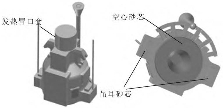
Fig.10 Initial optimization of the 3D model


Fig.11 Solid-state ratio analysis
5.2.3 Defect Analysis
In order to fully solve the problems of casting defects existing in the current gating system and ensure the quality of castings, the simulation defect analysis is carried out again on the optimized system, as shown in Fig. 12, it is found that the three isolated liquid phase zone parts analyzed by the solid-phase ratio all have shrinkage and porosity defects, and the defects are distributed in the three positions of the casting, and the wall thickness of these three parts of the casting is thicker, and a small hot joint is formed respectively, so it is necessary to speed up the cooling rate of these three places to avoid heat concentration; In addition, consider the overall heat dispersion of the sand mold and the intermediate sand The core dissipates heat faster.
5.2.4 Secondary optimization measures
Through the analysis of defects and causes after the initial optimization, in order to minimize the possibility of shrinkage porosity, the casting process is further improved as follows: (1) cold iron is set at the three defect positions of the casting, so as to speed up the cooling rate of the three places and avoid shrinkage defects; (2) Add an exhaust hole in the lower type to connect with the hollow position of the 1# large sand core, so that the heat inside the casting can be discharged faster, and the cooling speed of the lower part of the casting is faster, so that the upper riser shrinkage effect is better.
6 The design of the cold iron
6.1 Selection of the location and shape of the chilled iron
Cold iron can eliminate the local stress of the casting, has the function of increasing the riser shrinkage distance, and preventing cracks [1], combined with the structural characteristics of the lifting box and the simulation analysis results, the external cold iron is selected, and the cold iron is made of high-carbon steel. According to the simulation analysis, the cold iron is arranged at the three isolated hot joint parts, and the cold iron is arranged at the outer plane and the inner arc plane of the casting. The cold iron on the outer plane is formed cold iron, and the inner arc surface is special-shaped cold iron. The location of the cold iron is shown in Figure 13.
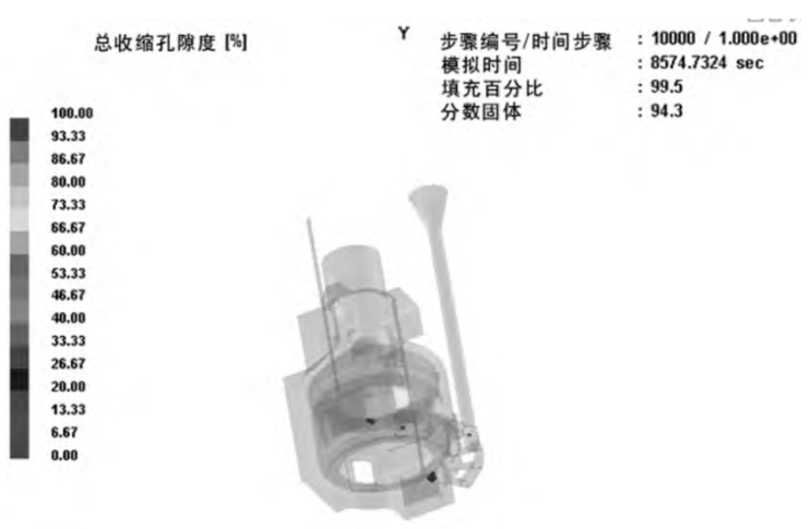
Fig. 12 Analysis of the defect
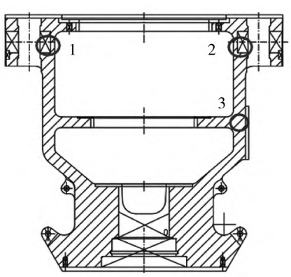
Fig. 13 Locations of additional chills required
6.2 Analysis of secondary optimization results
The simulation results show that there are no visible characteristic defects inside the casting, indicating that the improvement measures of setting cold iron and adding air holes to strengthen the internal heat dissipation of the casting are effective, and the casting process after the second optimization meets the predetermined requirements.
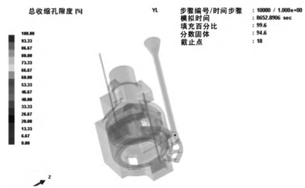
Fig. 14 Defect analysis
7 Conclusion
(1) According to the structure and size characteristics of the casting, the top is designed There are two types of gating systems: injection type and bottom injection type.
(2) Select after analyzing the casting defects according to ProCAST comparative simulation Bottom-injection pouring system, and added heat rise to the castings twice mouth, external cooled iron, and vent holes for process optimization.
(3) Numerical simulation analysis of the optimized casting, solid phase ratio The results showed that there were no obvious casting defects, and the castings were solidified sequentially The process improves the forming efficiency of castings and ensures the quality of castings.