The design of sand core head of intake cylinder is the most important content in sand core design, and also plays an important role in determining the quality of castings. The vertical and horizontal comprehensive design schemes are adopted.
The main functions and design principles of the core head are as follows:
① Ensure that the sand core can be accurately positioned and fixed in the core running process;
② It can bear the weight of sand core and the buoyancy of molten iron during pouring process to ensure that the sand core is not damaged such as fracture;
③ It is easy to set up an exhaust channel, and a large amount of gas produced by resin sand core can be discharged smoothly by means of vent holes. The general design and calculation of core head mainly include core length, slope, clearance, pressure ring and sand accumulation groove.
In addition to the length of the core head, other parameters can be selected by referring to relevant manuals and standards and combining with practical experience, which is relatively simple. It should be noted that the design of core head length is closely related to the buoyancy of molten iron, the strength and stiffness of sand core, and the cross-sectional area of sand core. The design should pay attention to the following points:
(1) When the horizontal core head is set, the larger the sand core is, the greater the buoyancy in molten iron will be. The length of core head is proportional to the size of sand core, and the buoyancy of 3 ා and 7 ා cores is the largest.
(2) The core of the steel core should be arranged on the top of the core or the bottom of the cylinder to avoid the impact of the core.
(3) For the three sand cores with the same structure, small size difference and equal cross-section, different slope and positioning should be set to avoid confusion and wrong direction in the subsequent core setting and molding process.
Based on the above factors, the inlet cylinder 2 ා, 4 ා, 5 ා and 7 ා are set as horizontal core head, and the rest are set as vertical core head. Here, the bearing area of the core head is calculated by taking the largest 7 ᦇ core as an example. The pressure bearing area of the core head shall be large enough to ensure that the allowable compressive stress is not exceeded under the maximum buoyancy of liquid metal. The pressure bearing area s of core head shall meet the following formula

Where
F-core – sand core bearing the maximum buoyancy;
K-safety factor, k = 1.3-1.5;
[pressure σ] – allowable stress of sand core, the dry sand mold can be taken as 0.6-0.8

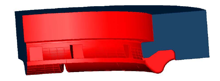
The outline of the core is shown in the figure. In the figure, the red surface is the contact surface between the sand core and molten iron, and the blue surface is the core head surface. The bearing area is calculated according to the formula.

The results show that the pressure bearing area of core head is 2.51610 × DM2, which satisfies the formula and meets the requirements of pressure bearing conditions of core head.
