
The bedside box is an important part of ordinary machine tools, mainly used for all kinds of machine tools to carry the operation of the cutter head, and it is necessary to minimize the axes Casting defects appear in the holes, intermediate support plates and bottom mounting surfaces, and their casting quality is directly related to the strength, machining accuracy and stability of the machine tool. By analyzing the structural characteristics of the headstock, it is sanded Gravity casting process design. The computer software was used to carry out multiple numerical simulations, and the optimal process parameters were analyzed, and the riser and cold iron were reasonably set, which significantly reduced the volume of shrinkage porosity of castings. It has certain guiding significance for enterprises to improve the quality and process yield of castings.
1 Structural and manufacturability analysis
The structure of the headboard box is complex, the mass of the blank is 173.6 kg, the contour size is 408 mm×345 mm×501 mm, the minimum wall thickness of the casting is located in the bottom groove of the casting, the thickness is 9.5 mm, and the wall of the spindle hole of the headboard box is the thickest part of the casting (about 87 mm), which is easy to form an isolated pool melt during the solidification process, resulting in shrinkage porosity defects, and the structure of the headboard box is shown in Figure 1.
2 Determination of casting process scheme
2.1 Selection of molding materials
The casting material is HT200, which is produced by furan resin sand, single piece small batch, and manual modeling, which has the advantages of high dimensional accuracy, high surface quality, and easy regeneration of old sand. The use of alcohol-based quartz powder coating to form an insulating coating on the surface of the mold and sand core can avoid defects such as sand sticking in the casting.
2.2 Determination of pouring position and parting surface
The pouring position refers to the position of the casting in the casting mold during pouring, and the selection of the parting surface should be consistent with the pouring position as much as possible according to the structural characteristics, size, weight, and technical requirements of the casting. The pouring position and parting surface of this casting are shown in Figure 2, with a large plane of casting at the bottom, the side of the casting and the outer contour of the bottom surface can be from above
The bottom box is formed, and it is easy to start the mold.
2.3 Design of sand core
This casting adopts upper and lower horizontal parting, and the outer contour is formed by the pattern. The 1# core is used to form the inner cavity and side shaft bore of the casting. Two horizontal cores and one cantilever core are respectively arranged at both ends of the 1# core spindle hole and the top surface for the installation and positioning of the 1# core and to prevent rollover. 1# The core shape is complex and needs to be formed using loose blocks. The loose block is assembled from the loose block 1, the loose block 2 and the loose block 3 using pins and grooves. The installation diagram of the 1# core and loose block is shown in Figure 3. The 2# core is used to form the bottom groove and oil outlet of the casting, the upper and lower cores are used for the installation and positioning of the 2# core, and the side view of the 2# mandrel is shown in Figure 4.
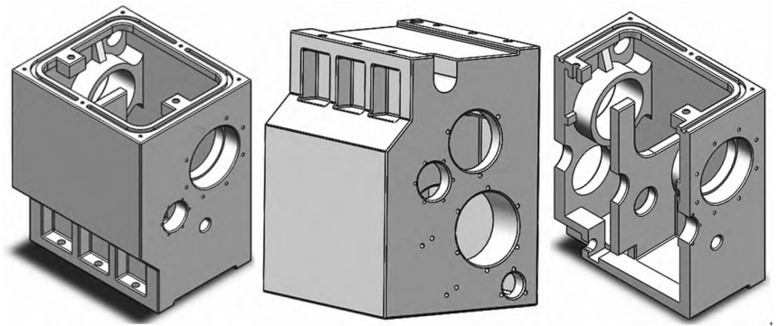
Figure 1 Three-dimensional view of the casting structure
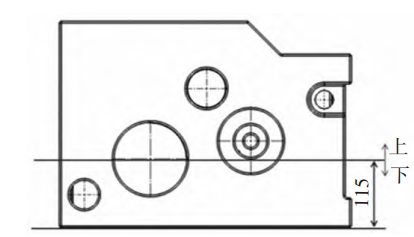
Figure 2 Schematic diagram of pouring location and parting surface location
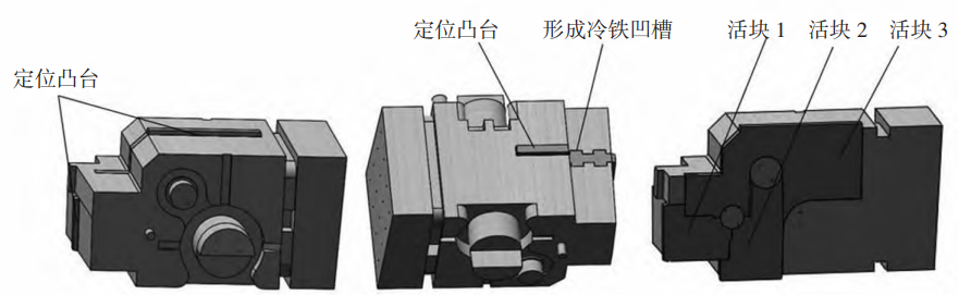
Figure 3 Schematic diagram of the installation of 1# cores and loose blocks
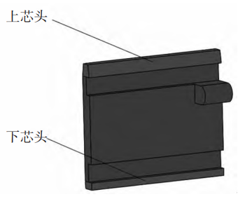
Figure 4 2# mandrel diagram
2.4 Design of the initial gating system
The gating system is a channel for molten metal to flow into the cavity from the pouring ladle, which is generally composed of a pouring cup, a straight sprue, a cross sprue and an inner sprue. This casting adopts a semi-closed bottom-injection gating system, a pool-type pouring cup is selected, and the horizontal sprue and inner sprue are buried pipe shapes. When the pouring of the casting is calculated
32 s; The cross-sectional area ratio of each runner is ΣF straight:ΣF horizontal:ΣF inner = 1.2:1.5:1, and the cross-sectional area of straight sprue, cross sprue and inner sprue is 9.6 cm2, respectively
, 6 cm2 and 4 cm2; After calibration, the liquid level rise rate is V-type =1.54 cm/s.
2.5 Numerical simulation process analysis
The above model was saved in IGS format and imported into the Pro cast software, and the mesh module was used to mesh, and a total of 1209825 six-body meshes were divided. According to the above analysis and actual production experience, the pouring process parameters are set, in which the initial temperature of the casting mold is 20 °C, the pouring temperature is 1380 °C, the heat transfer coefficient of the casting-mold is 500 W·m-·2 K-1, and the cooling mode is air cooling.
2.5.1 Filling velocity field analysis
The filling process of the casting is shown in Figure 5, and it can be seen that the height of the molten metal exceeds the inner sprue at 7.22 s, filling the bottom of the entire cavity, and the filling is about 25%; When the filling was 12.52 s, the liquid level rose steadily, and the filling was completed
up to about 80%; When the filling is 30.16 s, the filling is completed. The same color in the filling speed field (Fig. 5d) is distributed in horizontal bands, indicating that the whole filling process is stable, there is no large liquid level fluctuation, the filling effect is good, and the designed gating system basically meets the filling requirements of castings.2.5.2 Defect analysis of castings。


Figure 5 Simulation results of the filling process
2.5.2 Defect analysis of castings
The distribution of defects in the casting is shown in Figure 6, the total volume of shrinkage porosity is 129.3 cm3, which is mainly distributed in the thick wall of the spindle bore, the middle bearing plate and the spindle hole on the side near the inner gate, and the casting slice diagram is shown in Figure 7, which shows that there is a cavity at the top of the “pouring position” of the casting due to the volume shrinkage that occurs when the molten metal solidifies.
3 Optimization of process parameters
3.1 The influence of process parameters on the quality of castings
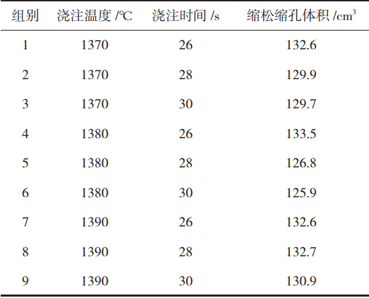
The molding quality of castings is affected by a variety of factors, the control variable method is adopted, according to the actual production experience, different pouring temperatures and pouring times are selected for numerical simulation, according to the simulation results, the volume, range and variance of shrinkage porosity defects of castings under different process parameters are counted, and the statistical data are shown in Table 1. It can be seen that the volume of shrinkage porosity defects in castings is more affected by the pouring temperature, and the data is more discretized. As shown in Figure 8, it can be seen that the pouring temperature is between 1360~1380 °C, and with the increase of pouring temperature, the volume of shrinkage porosity defects in the casting decreases sharply, and when the pouring temperature is 1380 °C, the volume of shrinkage porosity is the smallest. When the pouring temperature is between 1380~1400 °C, with the increase of pouring temperature, the volume of shrinkage porosity defects in the casting increases first and then decreases.
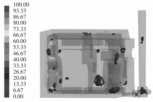
Figure 6 Initial scheme casting shrinkage porosity defect distribution diagram
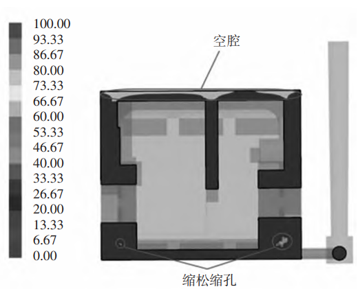
Figure 7 Initial Scheme Casting Slicing Diagram
Table 1 Data statistics under univariate variables
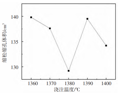
Figure 8 Effect of pouring temperature on casting quality
When the pouring time is 28 s, the volume of shrinkage porosity defects of the casting is the smallest, and when the pouring time is greater than 28 s, the volume of the shrinkage porosity defects of the casting increases sharply with the increase of pouring time.
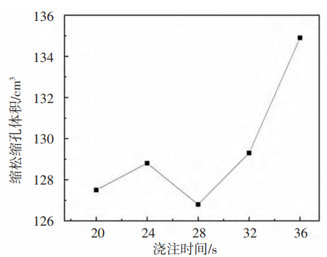
Figure 9 Effect of pouring time on casting quality
3.2 Orthogonal experiments
According to the experiment and analysis of the influence of the above single factor variables on the quality of castings, in order to further obtain more reasonable pouring process parameters, 9 groups of experiments were directly designed with pouring temperature and pouring time as influencing factors, and different process parameters were input respectively, and computer software was used to carry out numerical simulation and calculate the shrinkage porosity volume of castings, as shown in Table 2. Finally, the optimal number of pouring processes for the castings was determined: the pouring temperature was 1380 °C and the pouring time was 30 s.
Table 2 summarizes the results of the trial
4 Optimization and simulation of pouring process scheme
4.1 Optimization of pouring process scheme
According to the above analysis, the pouring time of the casting was determined to be 30 s, and the cross-sections of the straight, cross, and inner runners were 9.5 cm2, 11.9 cm2, and 7.5 cm2, respectively. Cold iron is set at key positions such as the spindle hole wall, the bottom of the intermediate bearing plate and the oil port of the casting, so as to speed up the local cooling rate and reduce the casting defects of the casting; A riser is placed at the top of the “pouring position” to compensate for the shrinkage of the casting Sink. The distribution of riser and chill iron locations is shown in Figure 10.
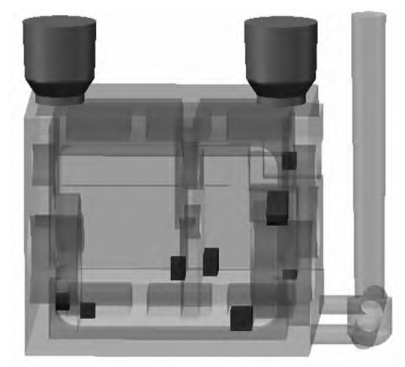
Figure 10 Riser and chiller location distribution
4.2 Results after process optimization
According to the optimized pouring process scheme, the numerical simulation was carried out by computer software, and the defect distribution of the casting was shown in Figure 11, which showed that the shrinkage porosity of the key parts of the casting, such as the spindle hole wall and the intermediate bearing plate shaft hole, was basically eliminated, and the total volume of the shrinkage porosity was reduced to 28.9 cm3, which significantly reduced the casting defects in the casting and improved
The quality of the casting. The slicing diagram of the casting after solidification of the molten metal after the process optimization is shown in Figure 12, and it is found that the riser shrinkage effect is very good, and there is no longer a cavity on the top of the casting. When the casting solidifies, the molten metal remains in the riser The amount is small, so that the process yield of this process scheme can reach 87.7%, which saves metal resources, reduces production costs, and significantly improves the quality of castings.
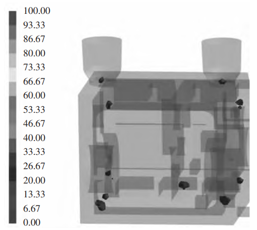
Figure 11 Pattern of shrinkage porosity defects in castings after process optimization
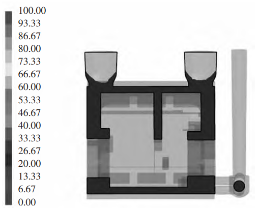
Figure 12 Casting slicing diagram after process optimization
5 Summary
(1) According to the structural analysis and work requirements of the casting, a semi-closed bottom-injection gating system with intermediate parting is adopted, ∑F straight: ∑ F horizontal: ∑F inner = 1.2: 1.5:1, in which the sprue, the cross sprue and the inner sprue The cross-sectional areas are 9.5 cm2 respectively , 11.9 cm2 and 7.5 cm2 。 The inner cavity of the casting is formed with an integral large sand core, which can improve the accuracy of the bedside box, effectively reduce the number of core boxes, and at the same time, the gating system is reasonable and simple, which is conducive to reducing the production cost of the factory.
(2) According to the experimental results of the analysis of single factor variables, the pouring temperature had a greater influence on the quality of castings, and the optimal pouring process parameters were determined through nine sets of experiments: pouring temperature 1370 °C and pouring time 28 s.
(3) In order to ensure the quality of the casting, place 2 risers at the top of the casting pouring position, with the riser size of ø120 mm ×110mm, and place them respectively near the spindle hole wall, the intermediate bearing plate and the oil port With 8 pieces of cold iron with a thickness of 20 mm and 10 mm, the final process yield is η=87.7%, which effectively avoids the occurrence of shrinkage porosity defects, ensures the compactness of key parts of the casting, and improves the quality of the casting
Measure.