
In the field of metal casting, lost foam casting represents a significant advancement over traditional sand casting methods. This process involves creating a foam pattern that matches the desired part geometry, coating it with a refractory material, placing it in a sand mold, and then pouring molten metal. During pouring, the foam pattern vaporizes and decomposes, allowing the metal to take its place and form the casting. Lost foam casting offers numerous benefits, including high dimensional accuracy, design flexibility, environmental friendliness, and high production efficiency. However, the complexity of metal flow during mold filling—where the metal must displace the foam pattern through softening, decomposition, and gasification—poses challenges that can impact casting quality. As such, the design of the gating system is a critical factor in ensuring the stability and quality of lost foam casting processes. In this article, I will explore the principles, calculations, and optimization strategies for gating systems in lost foam casting, drawing on theoretical knowledge and practical experience to provide a comprehensive guide.
The gating system in lost foam casting serves as the primary channel for molten metal delivery, and its design must address several key functions to ensure successful casting outcomes. Firstly, it must promote stable mold filling by minimizing turbulence, which helps prevent the entrapment of gases and slag. Secondly, it needs to facilitate the efficient removal of pyrolysis products from the decomposing foam pattern, thereby reducing the risk of defects such as collapse and carbon inclusions. Lastly, the gating system should support controlled solidification through proper thermal gradient management, enabling directional solidification and minimizing shrinkage defects. These functions are essential for achieving high-quality castings in lost foam casting, and they guide the overall design approach.
When selecting the pouring position in lost foam casting, several principles must be considered to optimize casting quality. Vertical or inclined pouring is generally preferred over horizontal upward pouring, as it reduces the likelihood of residue accumulation on upward-facing surfaces. For instance, in iron castings, this approach can decrease carbon defect rates by over 30%. Additionally, critical machining surfaces should be positioned at the bottom or sides of the mold, while non-critical surfaces are placed at the top to minimize slag and shrinkage issues. It is also important to ensure that blind areas within the sand mold achieve a dry sand compaction density of at least 85% to prevent mold collapse during pouring. These considerations are vital for maintaining the integrity of the casting in lost foam casting processes.
The choice of gating method in lost foam casting depends on the alloy type and the structural characteristics of the casting. Different alloys require tailored gating approaches to address their specific solidification and flow behaviors. For example, cast iron and ductile iron often benefit from bottom or side gating to reduce carbon defects in thick sections, while steel castings may require top gating with open risers to enhance feeding for shrinkage compensation. Aluminum alloys, with their thin walls and susceptibility to oxidation, are typically gated from the bottom or through stepped systems to ensure smooth filling. Complex thin-walled castings may employ vertical slot gating to minimize flow resistance. The table below summarizes these recommendations for common alloys in lost foam casting.
| Alloy Type | Recommended Gating Method | Purpose |
|---|---|---|
| Cast Iron, Ductile Iron | Bottom or Side Gating | Reduces carbon defects in thick sections |
| Cast Steel | Top Gating with Open Riser | Enhances feeding for high shrinkage demand |
| Aluminum Alloy | Bottom or Stepped Gating | Prevents oxidation and cold shuts in thin walls |
| Complex Thin-Wall Castings | Vertical Slot Gating | Minimizes filling resistance |
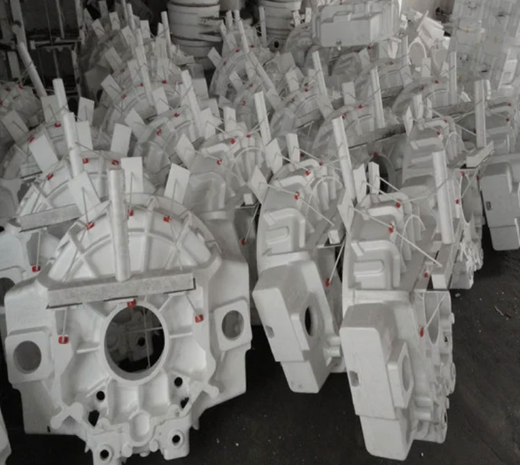
In a practical application of lost foam casting, I designed the gating system for a transmission housing casting, which is commonly used in commercial vehicles. The casting material was gray iron (similar to HT200), with overall dimensions of 463 mm in height, 500 mm in width, and 350 mm in depth. The wall thickness was 8 mm, and the casting mass was 86 kg. The foam pattern was produced using expandable polystyrene (EPS) beads with a density of 22–23 g/cm³, and a refractory coating was applied by dipping. The pouring temperature ranged from 1,460 to 1,510°C, and the process was conducted under a vacuum pressure of -0.07 to -0.03 MPa in a lost foam production line.
To determine the gating system dimensions, I first established the pouring position. Given the casting’s height of 463 mm, a bottom gating system was selected to promote stable metal ascent and reduce the risk of gas entrapment. The casting was oriented vertically in the sand mold with the rear face upward to facilitate sand compaction. The sprue height was set to 680 mm, accounting for a base sand thickness of 200 mm and a clearance of 50–150 mm below the mold top to allow for plastic film covering. This setup ensured efficient mold filling in the lost foam casting process.
The cross-sectional areas of the gating system components were calculated using the Osborne formula, which is derived from Bernoulli’s principle and continuity equations. This formula determines the choke area, which is the smallest cross-section in the gating system that controls the flow rate. The equation is expressed as:
$$ S_{\text{choke}} = \frac{m}{\rho t \mu \sqrt{2g H_p}} $$
where:
– \( m \) is the total mass of metal flowing through the choke (in kg),
– \( \rho \) is the density of the molten metal (in kg/m³),
– \( t \) is the total mold filling time (in s),
– \( \mu \) is the flow coefficient (dimensionless, typically 0.3–0.6),
– \( g \) is the acceleration due to gravity (9.81 m/s²),
– \( H_p \) is the average effective pressure head height during filling (in m).
For bottom gating systems, \( H_p \) is calculated as \( H_p = H_0 – P/2 \), where \( H_0 \) is the height from the sprue top to the casting top, and \( P \) is the casting height. In this case, the total mass \( m \) included the casting and gating system, estimated at 101 kg based on a yield of 85%. The density \( \rho \) was 7,000 kg/m³ for iron, and the flow coefficient \( \mu \) was taken as 0.5. The filling time \( t \) was derived from the empirical formula \( t = K \sqrt{m} \), with \( K = 0.85 \) under vacuum conditions, resulting in \( t = 8.54 \) s. The pressure head \( H_p \) was 0.452 m, leading to a choke area \( S_{\text{choke}} \) of approximately 11 cm².
In lost foam casting, a closed gating system is often used to prevent mold collapse due to gas generation from foam decomposition. The area ratios for the gating components were set as ingate : runner : sprue = 1 : 1.2 : 1.4. Thus, the total ingate area \( \Sigma S_{\text{ingate}} \) was 11.2 cm², the runner area \( \Sigma S_{\text{runner}} \) was 13 cm², and the sprue area \( \Sigma S_{\text{sprue}} \) was 15.3 cm². The sprue was designed as a cylindrical shape with a diameter of 45 mm, tapering to 80 mm at the top to match the pouring cup. The runner and ingates were symmetrically arranged, with two flat ingates (7 mm thick and 80 mm long) to increase the gas escape area and reduce flow resistance. The gating system was assembled using hot melt adhesive to ensure tight seals.
To prevent pattern deformation during handling, coating, and molding in lost foam casting, reinforcement ribs were incorporated. For the transmission housing, foam ribs were integrated into the pattern for the top cover surface to limit deformation to within 2 mm, and custom-sized glass fiber bars were attached to the rear face to maintain dimensional stability. These ribs were designed to account for shrinkage, with a 1% allowance added during pattern making.
Riser design is another critical aspect of lost foam casting, particularly for managing carbon defects and shrinkage at the casting top. Using simulation software, I identified the final solidification zones and designed a riser to collect slag and carbon residues. The riser diameter was set to 1.5–2 times the hot spot thickness of the casting, and the height was 1.2–2 times the diameter. Low-density foam was used for the riser to minimize gas evolution. The riser dimensions were optimized based on thermal analysis to ensure effective feeding and defect reduction.
In lost foam casting, the use of ceramic filters is essential for improving metal quality by removing inclusions. Analysis of defect areas in the transmission housing revealed high levels of oxygen, silicon, and aluminum, indicating contamination from coating and furnace materials. To address this, I incorporated a ceramic filter plate with a diameter of 60 mm and 10 pores per inch (PPI) into the gating system. The filter was positioned in the sprue, above the runner, and sealed with refractory tape to withstand metal冲刷. This implementation significantly reduced inclusion-related defects, enhancing the overall quality of the lost foam casting process.
The optimization of gating systems in lost foam casting can be further supported by mathematical models and empirical data. For instance, the filling time \( t \) can be refined using the formula:
$$ t = K \sqrt{m} $$
where \( K \) is a correction factor that varies with process conditions. In lost foam casting, \( K \) typically ranges from 0.8 to 1.0 under vacuum. Additionally, the flow coefficient \( \mu \) depends on the gating system geometry and mold resistance, and it can be estimated through experimentation. The table below provides typical values for key parameters in lost foam casting gating design.
| Parameter | Symbol | Typical Range |
|---|---|---|
| Flow Coefficient | \( \mu \) | 0.3–0.6 |
| Metal Density | \( \rho \) | 7,000 kg/m³ (iron) |
| Filling Time Factor | \( K \) | 0.85 (under vacuum) |
| Pressure Head Height | \( H_p \) | Depends on gating type |
In conclusion, the design of gating systems in lost foam casting requires a holistic approach that combines theoretical calculations, practical experience, and advanced simulation tools. By applying formulas like the Osborne equation and adhering to design principles such as proper pouring position and gating methods, it is possible to achieve stable and high-quality castings. The integration of reinforcement ribs, risers, and ceramic filters further enhances the reliability of the lost foam casting process. Through continuous optimization and the adoption of new materials, lost foam casting can meet the demanding requirements of modern industrial applications, providing a robust solution for complex casting production.
Overall, lost foam casting offers significant advantages in terms of precision and efficiency, but its success hinges on meticulous gating system design. As I have demonstrated through this case study, a methodical approach that includes calculation, simulation, and practical adjustments can lead to consistent results in lost foam casting. Future developments in lost foam casting will likely focus on refining these design strategies to overcome existing challenges and expand the applicability of this innovative process.