
Iron mold sand coated casting is mostly aimed at nodular iron castings, because the rigidity of iron mold can give full play to the eutectic expansion of nodular iron and densify the castings. The eutectic expansion of nodular iron castings is relatively strong, which can give full play to the advantages of iron mold sand coated casting process. Based on the parameters of iron mold sand coated casting gating system in the above table and combined with the corresponding casting analysis, the gating process design law of iron mold sand coated casting is summarized as follows:
(1) Ordinary sand casting usually has no riser, which plays the role of liquid feeding. The iron mold sand coated casting generally does not have a riser. This requires liquid feeding through the gating system. Therefore, the inner gate should be dispersed to form a widely distributed feeding channel.
(2) In sand casting with riser design, the slag inclusion in the casting can float up to the riser in liquid state. The slag inclusion defect in iron mold sand coated casting is more common, which makes the casting machining difficult, increases the cost and reduces the productivity. Therefore, special attention should be paid to the filtration of liquid metal.
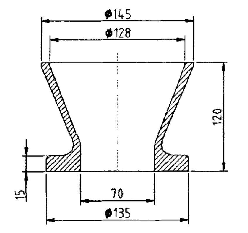
Restricted by the iron mold sand coated casting process, the sprue is basically conical, which is convenient for demoulding. The gate cup generally selects a simple funnel-shaped (as shown in Figure 1) or pool shaped structure. The funnel-shaped gate cup has the advantages of simple structure and convenient manufacture. Small capacity. It is conducive to saving liquid metal. And the feeding effect is good. However, its slag blocking effect is poor, and the ceramic grid filter board or foam ceramic filter plate should be placed at the bottom to serve the disadvantages of poor slag blocking effect.
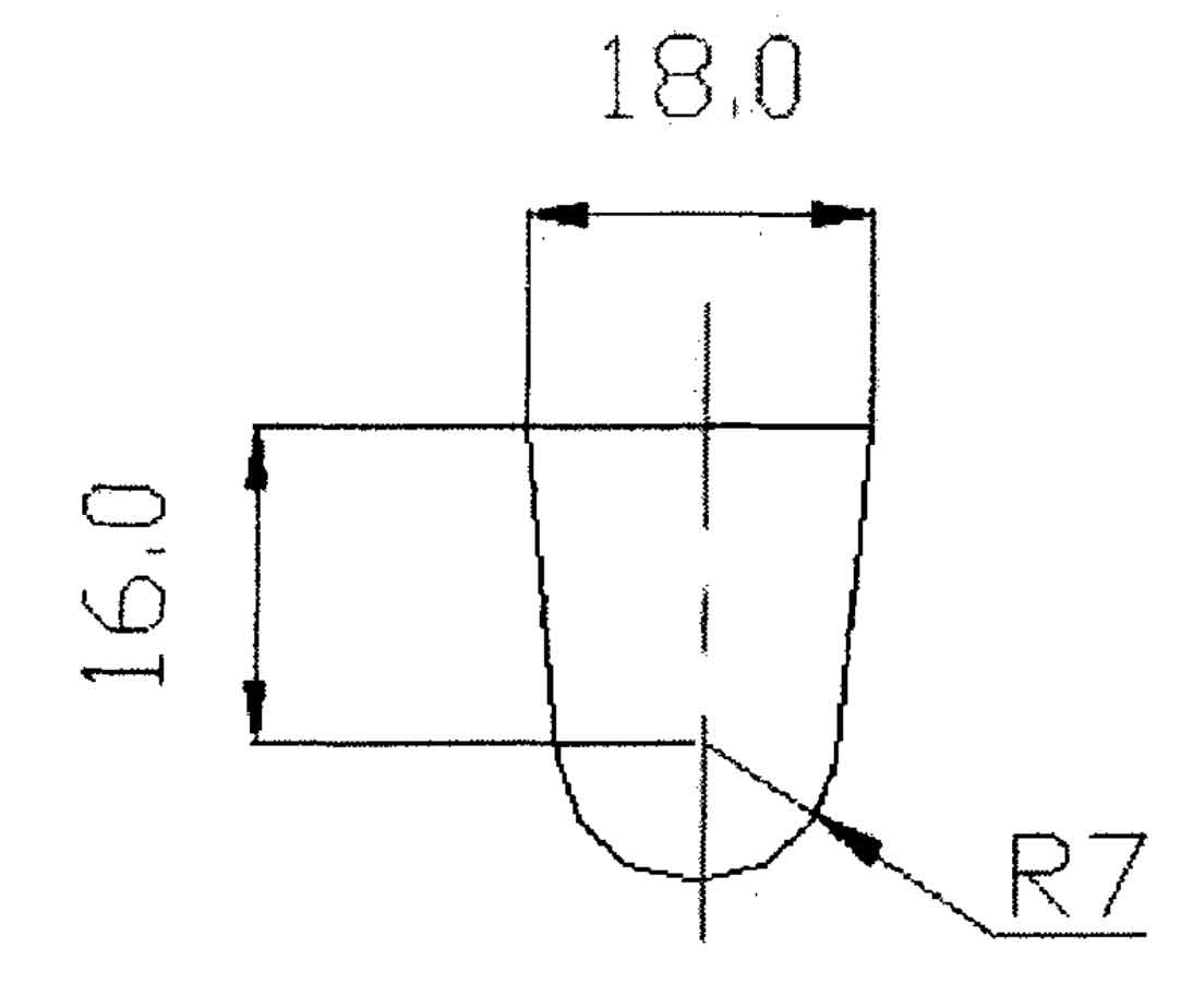
As the distribution medium from the sprue to the ingate, the runner is not only related to the structure of the casting itself, but also to the layout of the casting in the iron mold in the case of multiple parts in one mold. Generally, slag collecting bags or serrated protrusions (for slag blocking) are set at the outlet of the inner gate. Its section shape usually includes trapezoid, circle and dome trapezoid (as shown in Figure 2). The conditions for the transverse runner to effectively play the role of slag retaining are as follows:
a. The runner must be full;
b. The flow velocity of liquid metal flow in the runner shall be lower than the suspension velocity of slag inclusion;
c. The turbulent stirring effect of liquid metal flow is small;
d. The runner shall be of sufficient length. The end shall be lengthened, and its height shall be higher than that of the suction area of the ingate, so that the inclusion particles have enough time to float up to the metal surface without entering the cavity through the ingate.
Strengthening the slag retaining capacity of the runner mainly depends on changing the structure of the runner, increasing the resistance to liquid metal flow, slowing down its flow rate, preventing turbulent mixing and other measures.
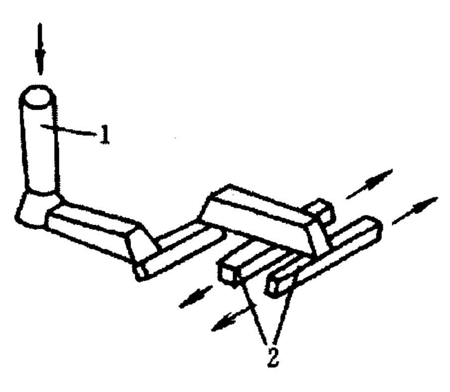
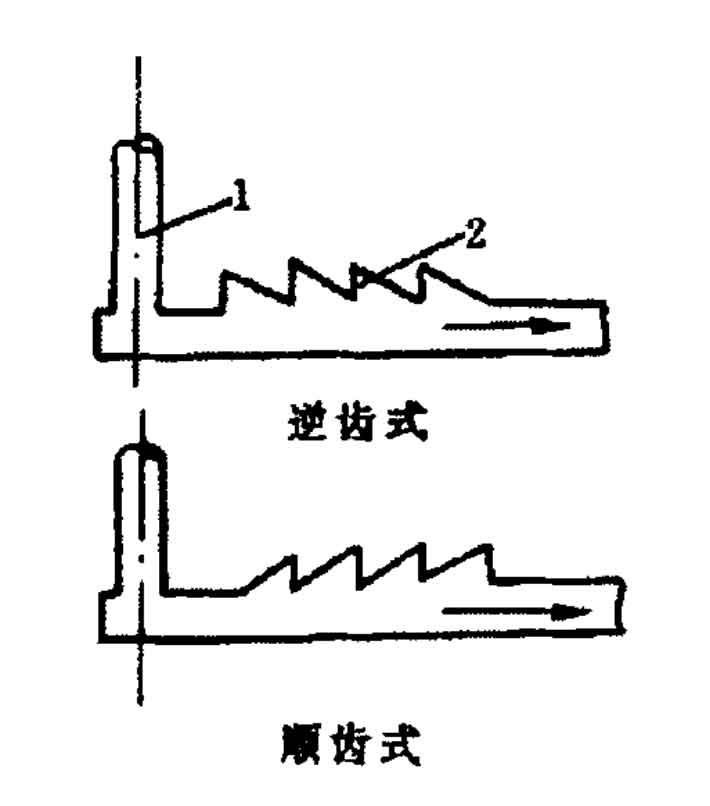
The slow flow gating system uses the turning of liquid metal in the runner to change its flow direction, so as to increase the flow resistance and reduce the flow rate (as shown in Figure 3). Or use the slag collecting ladle gating system, as shown in Figure 4. Locally increasing its thickness in the transverse runner is called slag collecting ladle. When the molten metal flows through the slag collector, due to the expansion of the section and the decrease of the flow rate, and the vortex is generated there, the inclusions are easy to float up and stay in the slag collector. The slag retaining effect of reverse tooth shaped slag collector is better than that of straight tooth shaped slag collector.
(3) In principle, sand casting can eliminate defects such as shrinkage cavity and porosity by sequential solidification, while iron mold sand coated casting needs to comprehensively consider the feeding and self feeding of castings. Therefore, balanced solidification must be adopted. Ensure that the gating system can give full play to the feeding function. The design of the inner gate shall ensure that it is unblocked before a large amount of graphitization expansion occurs in the casting, and the inner gate shall be closed in time. For example, for crankshaft castings, the inner gate mostly adopts arched section. The design of the inner gate is narrow and high, so that the gating system still has a certain feeding capacity after the completion of mold filling. When most of the castings solidify and eutectic expansion occurs, the inner gate solidifies first than the casting, which can prevent the non solidified molten iron from flowing back to the gating system. The distribution of the inner gate should be set in combination with the structural characteristics of the casting. Avoid such situations: the inner gate solidifies prematurely, the feeding effect of the gating system cannot be brought into play, or even the casting is not poured enough; or the inner gate is not closed in time, resulting in the backflow of the non solidified metal liquid in the casting under the action of solidification expansion.
(4) For the liquid feeding of castings, attention should also be paid to the role of the static head of the gating system. When the gating system of iron mold sand coated casting is not designed properly, the phenomenon of insufficient liquid feeding will appear. For small cast iron parts, the liquid feeding can be enhanced by increasing the static head to reduce the tendency of shrinkage cavity and porosity. When the height of the iron mold is low, the gate cup can also be used to increase the static head of the liquid metal and improve the feeding effect on the casting.
(5) The gating system shall be designed to facilitate the discharge of gas in the mold. Each component and structure of the gating system shall be as compact as possible to shorten the process:
(6) Larger sectional area ratio of gating system components should be selected.
Closed and open gating system is often used in production: Σ f transverse ≥ f straight ≥ Σ f inner. In such a gating system, the sprue is generally an inverted cone with large top and small bottom. Can quickly fill the mold. However, the cross-sectional area of the runner is the largest. The longer time of filling the cavity can effectively reduce the flow rate and ensure the smooth filling from beginning to end.