
The front bearing block is an important component of the front suspension system of a car, and is usually installed above the chassis to support and fix the bearings that rotate the front wheels. In the field of aviation, the landing gear of an aircraft also requires the use of a front bearing block to support and fix the wheels of the aircraft. The function of the front bearing block is to maintain a stable connection between the wheel and the suspension system, provide bearing support for wheel support and movement, and thus make the vehicle ride more smoothly and comfortably. The front bearing block usually has sufficient strength and rigidity to withstand various forces and loads during vehicle driving. Grey cast iron is a commonly used casting alloy material with characteristics of easy casting and good mechanical properties, suitable for applications that withstand small and medium loads and shocks, with good seismic performance, good processability, and low cost. It is suitable for use in the fields of parts and mold manufacturing, automotive components, and mechanical structures. The front bearing block mainly plays a connecting role, with complex stress conditions. In order to ensure that the part has good comprehensive performance, casting defects such as shrinkage porosity, gas porosity, and sand inclusion should be avoided during casting. By analyzing the structural characteristics of the casting, the pouring system, risers, chillers, and other parts of the front half of the bearing block are designed. The casting simulation software ProCAST is used to simulate and analyze the filling of metal liquid, solidification heat transfer, and shrinkage porosity defects during pouring. Considering the structural characteristics of the casting and optimizing the pouring system multiple times, the size and location of risers and chillers are analyzed and optimized through simulation results. The purpose of preventing and eliminating casting defects such as shrinkage porosity is finally achieved by analyzing and optimizing the results.
Process analysis of parts
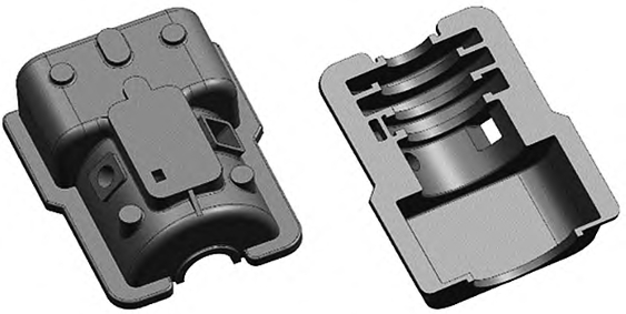
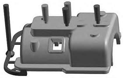
The three-dimensional structural solid diagram of the upper support bearing of the front bearing seat, which fixes the outer ring of the bearing, is shown in Figure 1. The overall dimensions are 1085mm×810 mm×380 mm, with a maximum wall thickness of 150 mm and a minimum wall thickness of 20 mm, and a net weight of 566 kg. The cavity structure is complex, and it is difficult for the molten metal to fill the mold. Moreover, the wall thickness difference at some structural turning points is large, which is prone to generate hot spots. The oil injection hole is a slender arc-shaped cavity, making it easy for the sand core to be damaged during the filling of the molten metal. The overall structure of the part is relatively symmetrical, and the upper and lower large surfaces are important processing surfaces. Technical requirements for castings do not allow shrinkage, porosity, gas porosity, sand inclusion and other defects that affect the performance. The upper half of the front bearing seat belongs to medium-sized castings, which are produced in small batches using manual molding production methods. In order to ensure high dimensional accuracy and surface quality of the castings, the molding material is selected to be furan urea formaldehyde resin sand with high bonding strength, good heat resistance, and low gas generation. According to the casting technical requirements, the parameters of the casting process are selected as follows: dimensional tolerance grade CT13, machining allowance G, casting shrinkage rate 0.9%, and cutting allowance for risers 3 mm. Based on the quality and wall thickness of the castings as well as the process manual, it is found that the cooling time of the castings is 1h.
Epilogue
The upper half of the front bearing seat of the casting was formed through a series of process design and numerical simulation analysis, resulting in a casting with no shrinkage and minimal defects. The main processes are: (1) The pouring method is selected as bottom pouring, and the pouring system is selected as semi-closed pouring system. This pouring method has stable filling and greatly reduces the occurrence of defects; (2) Through preliminary numerical simulation analysis, it is found that the main defects of the casting are concentrated at the top. Observe the final place where the metal liquid reaches and add risers at the corresponding position on the top. The risers have three main purposes, namely to achieve the effect of shrinkage compensation, to avoid shrinkage holes caused by different solidification sequences at the top, and to achieve the effect of gas exhaust; (3) The principle of adding chill iron in this design is to add it as needed, add it accurately, and add as little as possible. Therefore, we only added two chill irons on both sides of the casting, which perfectly eliminated the defects at this location.