Parting surface refers to the joint surface between two mold components in the casting process of tractor box. Parting surface is required for various casting methods (except ground soft bed modeling, open cast small parts and investment casting). The simplified scheme has a direct impact on the correct selection of the casting process of the tractor. The selection of parting surface and pouring position of tractor box casting should be considered at the same time.
When selecting the parting surface of tractor box casting, pay attention to the following principles:
(1) All or most of the tractor box castings, the machining surface of the tractor box castings and the machining datum shall be placed in the same box to reduce the dimensional deviation of machining positioning.
(2) To minimize the number of parting surfaces, especially in machine modeling, generally select a parting surface.
(3) In order to facilitate the mold lifting, the parting surface should be selected at the maximum section as far as possible. For the higher tractor box castings, try not to make the tractor box castings too high in one box, so as to avoid the inconvenience of sand filling, compaction and mold lifting; The number of sand cores shall be reduced as much as possible.
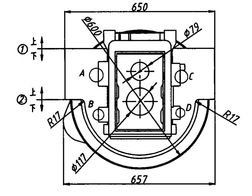
It can be seen from the above principles that because the casting of the tractor reducer box is high and the base at the lower end of the reducer box is a circular boss, the way of vertical placement of the tractor box casting up and down is excluded, so it can only be placed horizontally. As shown in Figure 1, the casting of tractor box is placed in two box shape. When the parting surface position of the tractor box casting is ①, because the base at the lower end of the reducer box body is circular, the superior arc boss in the upper sand box and the inferior arc boss in the lower sand box, the tractor box casting cannot be taken out; No matter the parting surface position of the tractor box casting is ① or ②, the bosses a, B, C and D marked in Figure 1 on both sides of the reducer box will cause the tractor box casting to fail to lift the mold. Although the use of corresponding movable blocks on both sides can solve this problem, this process is easy to lead to the increase of movable blocks.
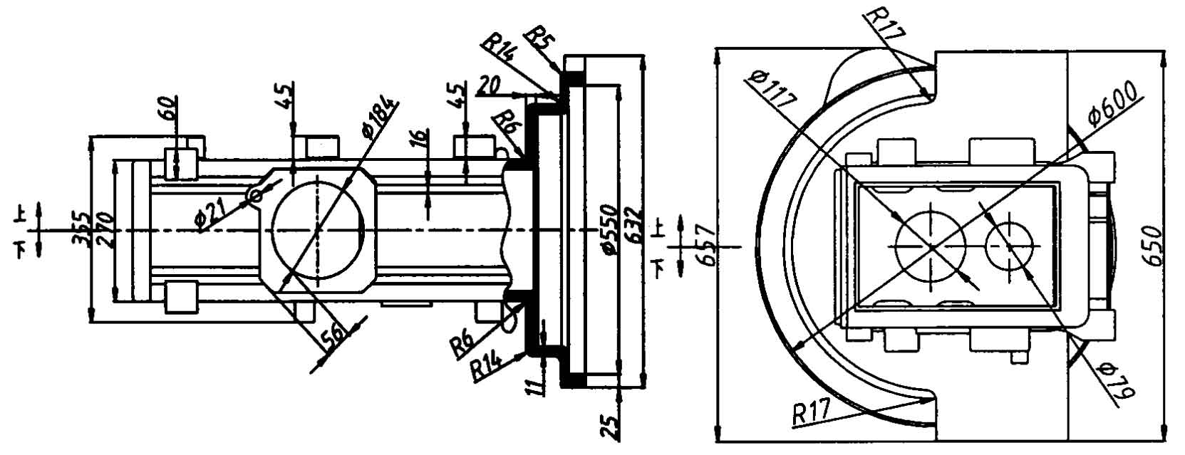
For the casting of tractor reducer case body, the position of the parting surface of the casting is shown in Figure 2. The horizontal parting method is adopted. The two box modeling is adopted, and the parting surface is located at the symmetrical center of the left and right sides. This parting method is convenient for unpacking and mold lifting, and there is no need to set movable blocks for bosses a, B, C and D on both sides, which reduces the number of movable blocks. The bosses on both sides are set with draft angle ≤ 2.


