
In the manufacturing of large-scale industrial equipment, the production of gear blanks poses significant challenges, particularly when dealing with heavy-section components. Traditional methods such as forging or welding often entail high costs, complexity, or limitations in shape and size. As a result, ductile iron casting has emerged as a viable alternative due to its excellent damping capacity, wear resistance, and cost-effectiveness. However, heavy-section ductile iron castings, such as gears with substantial wall thickness, are prone to defects like graphite degeneration, shrinkage porosity, and poor mechanical properties during prolonged solidification. To address these issues, we embarked on a project to develop a segmented manufacturing approach for a large ductile iron gear casting, optimizing the process through numerical simulation, precise chemistry control, and enhanced inoculation techniques. This article details our comprehensive methodology, from design to validation, emphasizing the critical role of ductile iron casting in achieving high-integrity components.
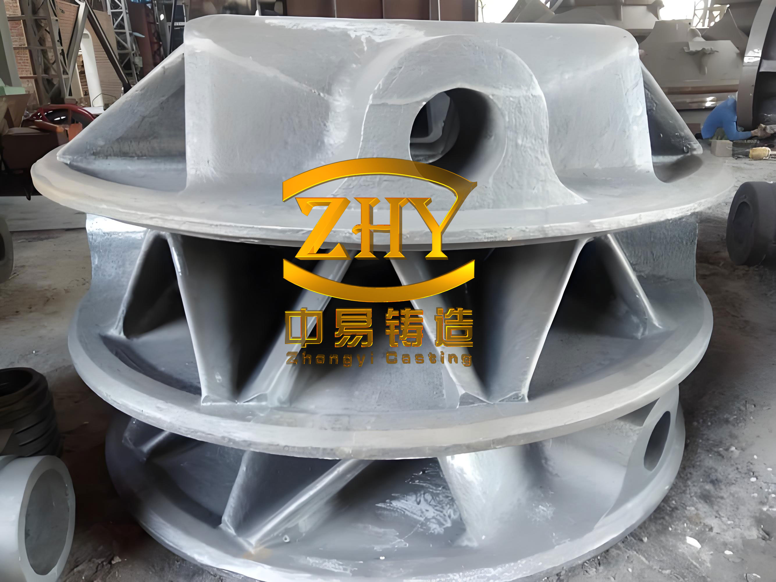
The gear in question required a material grade of QT700-2A, with a maximum wall thickness of 145 mm, classifying it as a heavy-section ductile iron casting. To reduce production cycle time and costs, the full gear was divided into sixteen segments, each with a chord length of 1,340 mm, width of 460 mm, height of 315 mm, and weight of 820 kg. Each segment included attached test blocks for quality assessment, and all machined surfaces mandated 100% ultrasonic and magnetic particle inspection per GB/T 34904—2017 and GB/T 9444—2019 standards, aiming for Grade 2 acceptance. This segmentation strategy underscores the adaptability of ductile iron casting for large, complex parts.
Central to the success of any ductile iron casting is the meticulous design of its chemical composition. For heavy-section applications, the carbon equivalent (CE) must balance graphitization promotion with avoidance of graphite flotation. We adhered to a high-carbon, low-silicon principle, targeting CE near the eutectic point. The CE is calculated using the formula: $$CE = C + \frac{Si + P}{3}$$ where C, Si, and P are weight percentages. Aiming for a CE of approximately 4.3–4.5, we optimized element ranges to ensure sound microstructure. Silicon, while strengthening through solid solution, was limited to prevent chunk graphite formation. Manganese, though enhancing strength and pearlite formation, was restricted due to its tendency to segregate and form carbides at grain boundaries, impairing toughness. Sulfur and phosphorus were minimized as harmful elements, with sulfur kept below 0.02% to aid nucleation without hindering nodularization, and phosphorus below 0.05% to avoid phosphide eutectics and cracking. Alloying elements like copper and molybdenum were incorporated to improve pearlite formation, uniformity, and hardenability, while chromium was controlled to prevent excessive carbide formation. Magnesium and rare earth (RE) residuals were carefully managed for effective nodularization, targeting Mg residuals of 0.04%–0.06% and RE residuals of 0.01%–0.03%. The finalized composition is summarized in Table 1.
| Element | Target Range | Rationale |
|---|---|---|
| C | 3.5–3.8 | Promotes graphitization, high CE |
| Si | 1.9–2.3 | Solid solution strengthening, limited to avoid chunk graphite |
| Mn | 0.4–0.6 | Enhances strength and pearlite, but minimized for segregation control |
| P | ≤0.05 | Minimized to prevent phosphide eutectics and shrinkage |
| S | ≤0.02 | Low for better nodularization, but aids nucleation |
| Cu | 0.4–0.6 | Promotes pearlite, improves uniformity |
| Mo | 0.1–0.3 | Enhances hardenability and strength |
| Cr | <0.3 | Limited to avoid excessive carbides |
| Mg (residual) | 0.04–0.06 | Essential for graphite nodularization |
| RE (residual) | 0.01–0.03 | Neutralizes trace elements, aids nodularization |
The casting process was tailored to address the thick section of the gear segment. We employed a vertical molding strategy with a two-part sand mold, ensuring accurate alignment via a parting line. The outer cylindrical surface, a critical machining area, was cast solid without core prints for holes. To manage thermal gradients and promote directional solidification, chill plates were strategically placed around the segment. These chills, prepared through shot blasting and baking, facilitated faster cooling in thick regions, leveraging graphite expansion for self-feeding. Three insulating risers were set atop the casting to provide adequate feeding, complemented by eight vent holes of Ø30 mm to release gases. The gating system was designed as a bottom-pouring, open type using ceramic sleeves to minimize turbulence. Patternmaking utilized red pine for robustness, with all fillets incorporated into the pattern. The molding material consisted of phenolic-modified furan resin no-bake sand, coated with alcohol-based paint, and resin content was optimized for strength while minimizing gas evolution.
Numerical simulation played a pivotal role in validating our ductile iron casting process. By employing commercial software, we modeled solidification dynamics to predict defect formation. The simulation parameters included a mesh size of 10 mm, time steps of 30 s, initial temperature of 1,350°C, and end temperature of 800°C, based on the Fe-C phase diagram and prior experience. The analysis focused on the mid-plane of the thick section, revealing a progressive solidification front from bottom to top, driven by chills. This ensured that shrinkage defects were confined to the risers, affirming a sound sequential solidification pattern. The porosity distribution, quantified as minimal and scattered, with only isolated points in non-critical areas, confirmed the工艺’s efficacy. The simulation output can be expressed through the thermal gradient equation: $$\nabla T = \frac{\partial T}{\partial x} + \frac{\partial T}{\partial y} + \frac{\partial T}{\partial z}$$ where $\nabla T$ dictates feeding efficiency. Additionally, the Niyama criterion, often used to predict shrinkage, is given by: $$N_y = \frac{G}{\sqrt{\dot{T}}}$$ where $G$ is the temperature gradient and $\dot{T}$ is the cooling rate. Values above a threshold indicate reduced shrinkage risk, which our simulation upheld.
Moving to the试制 phase, the melting and pouring processes were critical for achieving high-quality ductile iron casting. We used a medium-frequency induction furnace, charging with high-purity pig iron, clean scrap steel, returns, and ferroalloys. The pig iron followed a “one high, three low, one少” principle: high carbon, low Mn, P, and S, and low Si to maximize returns and inoculation efficiency. This selection minimized trace elements that could interfere with nodularization. The treatment involved a sandwich method with 3-8 nodularizer (20–30 mm size), and inoculation was intensified through stream inoculation (using Si-Ba inoculant) plus floating silicon inoculation (using 20–30 mm ferrosilicon). This dual approach enhanced graphite nodule count and roundness. Pouring was conducted at 1,310–1,350°C, with the entire process from treatment to completion within 20 minutes to prevent fading. The relationship between fading time and nodularization quality can be approximated by: $$Q = Q_0 e^{-kt}$$ where $Q$ is nodularization efficacy, $Q_0$ is initial efficacy, $k$ is a rate constant, and $t$ is time. Our tight control ensured $Q$ remained high.
Heat treatment was essential to achieve the required mechanical properties. We applied a quenching and tempering cycle: austenitizing at 860 ± 10°C for 6 hours followed by oil quenching, and tempering at 520 ± 10°C for 6 hours with furnace cooling to below 150°C. This refined the microstructure, promoting a mix of pearlite and ferrite. The kinetics of phase transformation during heat treatment can be described by the Avrami equation: $$X = 1 – \exp(-kt^n)$$ where $X$ is the transformed fraction, $k$ and $n$ are material constants. For ductile iron casting, this ensured a homogeneous matrix with minimal residual stresses.
Post-production检验 involved comprehensive testing of the ductile iron casting segments. Visual and dimensional inspections confirmed adherence to specifications. The attached test blocks were analyzed for microstructure and mechanical properties. Metallography revealed a nodularity exceeding 90%, graphite size grade 6, and a matrix comprising pearlite, ferrite, and minimal carbides. Mechanical tests, averaged over three samples, demonstrated superior performance versus standards, as summarized in Table 2. Ultrasonic and magnetic particle inspections showed no disqualifying defects, meeting all technical requirements for ductile iron casting in gear applications.
| Property | Standard Requirement (QT700-2A) | Measured Average Value |
|---|---|---|
| Tensile Strength (MPa) | ≥700 | 815 |
| Yield Strength (MPa) | ≥420 | 670 |
| Elongation (%) | ≥2 | 5 |
| Brinell Hardness (HBW) | 240–305 | 275 |
The success of this project underscores the viability of segmented manufacturing for large ductile iron casting components. By integrating simulation-driven design, optimized chemistry, and robust processing, we produced a heavy-section gear segment that fulfills stringent industrial standards. The ductile iron casting exhibited excellent nodular graphite structure, balanced microstructure, and superior mechanical properties, validating our approach. Furthermore, the use of numerical simulation allowed pre-emptive optimization, reducing trial-and-error cycles and costs. This experience provides a valuable framework for future projects involving ductile iron casting, particularly for thick-walled applications like gears, housings, or mill components. In summary, ductile iron casting, when meticulously engineered, offers a cost-effective and high-performance solution for heavy-section parts, with segmentation enabling scalability and efficiency.
To delve deeper into the material science aspects, the solidification behavior of ductile iron casting can be modeled using the Fourier heat conduction equation: $$\frac{\partial T}{\partial t} = \alpha \nabla^2 T$$ where $\alpha$ is thermal diffusivity. For heavy sections, the long solidification time $t_s$ can be estimated by: $$t_s = \frac{V^2}{4\alpha}$$ with $V$ as characteristic volume. This highlights the need for chills to modify $t_s$ and avoid defects. Additionally, the graphite nodule count $N$ per unit area relates to inoculation efficacy and cooling rate $\dot{T}$: $$N = A \cdot \exp(-B/\dot{T})$$ where $A$ and $B$ are constants. Our intensified inoculation aimed to maximize $N$, ensuring fine graphite distribution.
In terms of economics, the ductile iron casting process demonstrates advantages over alternatives. The relative cost $C$ can be expressed as: $$C = C_m + C_p + C_t$$ where $C_m$ is material cost, $C_p$ is processing cost, and $C_t$ is tooling cost. For ductile iron casting, $C_m$ is lower due to iron’s abundance, $C_p$ is reduced via segmentation, and $C_t$ is moderate compared to forging dies. This makes ductile iron casting attractive for large-scale production. Moreover, the environmental impact of ductile iron casting, considering energy consumption $E$, can be approximated by: $$E = \int P(t) dt$$ where $P(t)$ is power usage over time. Induction melting, coupled with optimized cycles, minimizes $E$, aligning with sustainable manufacturing goals.
Future work on ductile iron casting could explore advanced alloying, such as nickel additions for low-temperature toughness, or computational optimization of chill layouts using machine learning. The integration of real-time monitoring during pouring could further enhance quality control. In conclusion, this project not only achieved a specific gear component but also contributed to the broader knowledge base of ductile iron casting technology, paving the way for more innovative applications in heavy industry.