
1 Technical Requirements
The appearance of the split 9AT differential housing is shown in Figure 1, the design weight of the finished product is 2.32 kg, and the design weight of the blank is 3.32 kg, which is different from the conventional differential housing design with 2 windows and 2 pin holes. The differential housing is designed with 4 windows and 3 pin holes, while 3 asymmetrical bosses are designed at the flange face (as shown in Figure 1). The casting material grade is QT600-M (enterprise standard), the chemical composition is shown in Table 1, the dimensional tolerance and defect requirements are shown in Table 2, and the material requirements are shown in Table 3. The differential housing The body misalignment requirement is ≤ 0.5 mm, and the misalignment requirement is high; With a large diameter of φ161 mm, a blank flange thickness of 8.3 mm, and a low weight per piece, the DISA boxless moulding line was chosen for a variety of reasons. During the development phase, metallographic, hardness, and porosity detection locations are shown in Figure 2, including shaft head and flange R-angle locations; 100% X-ray flaw detection is required at the sample stage, and X-ray flaw detection must meet ASTM E-446 ≤ level2. meantime The customer performs a CT inspection of the inside of the finished product, which requires that the internal defects meet the requirements of D3/1 (i.e., the defect area is less than 3% of the maximum square area of the cross-section, and the maximum diameter of a single defect is less than 1 mm).
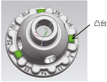
Fig.1 picture of DIFF case
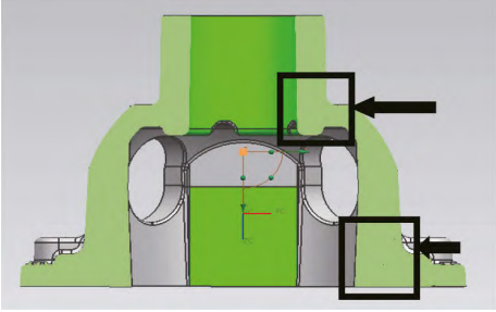
Fig.2 DIFF case sampling position
Tab.1 Chemical composition (mass fraction, %)

Tab.3 DIFF case dimensional tolerances and defect requirements

2 Process plan
Based on the thin flange design thickness of the differential housing, the large number of window and pin holes, and the high internal porosity requirements of the client, the preliminary process design adopts a double riser scheme, as shown in Figure 3. That is, a riser is set up at the flange position corresponding to the two pin holes on the casting. According to the casting Weight and structural size, the design of rectangular riser improves the process yield, the edge of the rectangular riser is rounded R10 to deduplicate, and the middle position is reasonably arranged to set up a common riser, and finally the design scheme of 2 castings corresponding to 3 risers is adopted. Based on the results of multiple single simulations, the size of the single-use riser on both sides was selected as 120 mm×43 mm×50 mm, in order to achieve the best shrinkage effect, the riser neck was designed according to the maximization design, the height of the riser neck was 7.7 mm, and the length of the riser neck was 55 mm, that is, the cross-sectional area of the riser neck reached 423 mm2. In order to reduce the weight of the riser monomer and meet the needs of liquid feeding, a 15 mm deweighting pressure groove is designed at the top of the riser, a separation block is designed at the bottom of the riser, and the height of the separation block is 15 mm, and the weight of the single riser design on both sides is 2.1 kg and the module is 6 mm. Similarly, the middle common riser is designed with reference to a single riser, with a common riser size of 120 mm× 55 mm×50 mm, a bottom pressure groove of 15 mm, and a separation block height of 15 mm. In order to improve the appearance quality of the differential housing, the gating system adopts a lap design, the vertical cross sprue and the horizontal cross sprue are lapped once, the vertical cross sprue is lapped again through a 6 mm sheet, and finally the inner sprue and the vertical cross sprue are lapped three times, and the lap is made through multiple lap joints The sprue with thin thickness and wide width is used to achieve the function of blocking flow and slag retention; Finally, the inner runner feeds iron from the bottom of the riser to slow down the impact of the molten iron flow rate on the sand mold and avoid impurities from entering the casting cavity during the filling process, so as to improve the appearance quality of the differential housing.
In order to ensure that the shrinkage porosity of the shaft head position meets the defect requirements of D3/1, according to the actual development experience, the shaft head position filling process is adopted for the shrinkage porosity and shrinkage porosity of the isolated hot joint at the shaft head position of the differential housing, and the shaft head does not need to be filled completely, only 60% is filled, that is, the height of the entire shaft head is 48 mm, and the filling of 29 mm can reach the target. In order to reduce the consumption of the sand core, a part of the inner cavity of the shaft head is formed by the outer mold, the diameter of the inner hole is φ39 mm, in order to facilitate the molding, the corresponding position is designed with 14 mm of outer mold forming, and the starting angle is designed to be 15°, and the filling position is then processed together with the shrinkage hole and shrinkage porosity by machining, so as to realize the position of the shaft head without shrinkage porosity and shrinkage defects. Considering the flange shrinkage at the riser position, the thickness subsidy of the corresponding flange position is 0.5 mm, which is also conducive to the shrinkage of the casting. At the same time, a cold needle is set at the position of the pin hole, the size of the cold needle is φ6 mm×25 mm, and the starting angle is 3°.
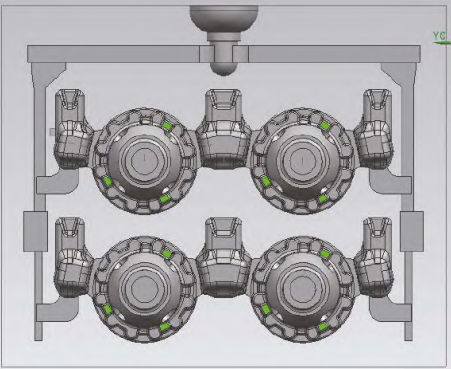
Fig.3 Schematic of process puring system
The results of simulated porosity and porosity defects are shown in Figure 4, the shrinkage porosity at the pin hole position is 2.6 mm3 and 11.0 mm3, the shrinkage porosity at the flange position is 0.7 mm3, and the shrinkage porosity at the plug shaft head position can be machined out at the core. In order to meet the internal crater defect simulation to 0, the scheme is continuously improved.
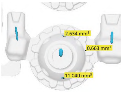
Fig.4 Simulation result
Rotate the casting 90°, after rotation, two of the 3 bosses of the casting are close to the riser position, and the riser is no longer facing the pin hole position of the casting, but facing the window position, and the cold needle is canceled at the same time, and the adjusted scheme is shown in Figure 5 As shown in Figure 6, the simulation results are shown in Figure 6, and it can be seen that there is no shrinkage hole at the position of the casting pin hole, and the shrinkage hole size at the position of the plugging shaft head is 77.8~80.00 mm3, which can be processed and removed.
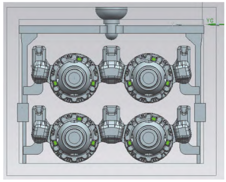
Fig.5 Adjusted process
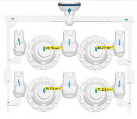
Fig.6 Simulation results of the adjusted process
3 Sample trial production and improvement
In the process of trial production using the above scheme, it was found that the pouring time was long and unstable, and the pouring time required 13~16 s, which affected the on-site molding production cycle. The sample was tested, and the appearance and size were all qualified, and the full-mold material and porosity were qualified; 100% X-ray flaw detection, no internal defects; The client’s third-party CT test is qualified, and the process is optimized for the problems existing in the trial production: simulating the filling time The difference between the actual pouring time and the actual pouring time is 5~8 s, which affects the production cycle, and the process yield is low, only 36.7%. The analysis is the effect of exhaust gas, due to the large volume of the sand core of the differential housing, the burning of the sand core during the pouring process will produce gas, and the gas will have an impact on the pouring time. The new process scheme adds exhaust flap exhaust to the horizontal sprue, and at the same time makes the bottom of the exhaust flap into a separator block for use. In order to improve the yield, cancel two sections of vertical cross sprue, and carry out weight reduction treatment on horizontal cross sprue simultaneously, and the inner sprue directly enters the iron from the top of the riser, and the inner sprue of the inlet and riser is lap treatment, and the new improved process scheme is shown in Figure 7. The new improved process simulates the pouring filling time of 8.539 s, and the pouring filling time of the subsequent actual production is 10.2~10.3 s, which can meet the on-site production cycle, and the process yield is increased from 36.7% to 42.7% by reducing the sprue and optimizing the gating system. The main reason for the overall low yield of the process is that the casting has a large diameter and thin thickness, in order to meet the internal defects requirements, add risers for retraction.
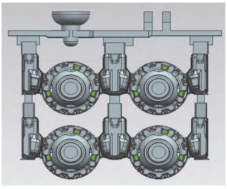
Fig.7 Improved process
4 Conclusion
During the trial production process, no shrinkage porosity defects were found in the internal X-ray flaw detection of the product, and the appearance was good. The castings have been mass-produced, and there are 1 887 pieces of appearance inspection and 62 pieces of scrap products in a month, with a pass rate of 96.71%. Among them, 37 pieces of appearance trachoma, Scrap rate 1.96%; 18 were bruised and bruised, with a rejection rate of 0.95%; After shot blasting, 7 pieces of unclear casting words, with a scrap rate of 0.37%; Less than 1% of the processing scrap rate at the customer end meets the goal of product development.