
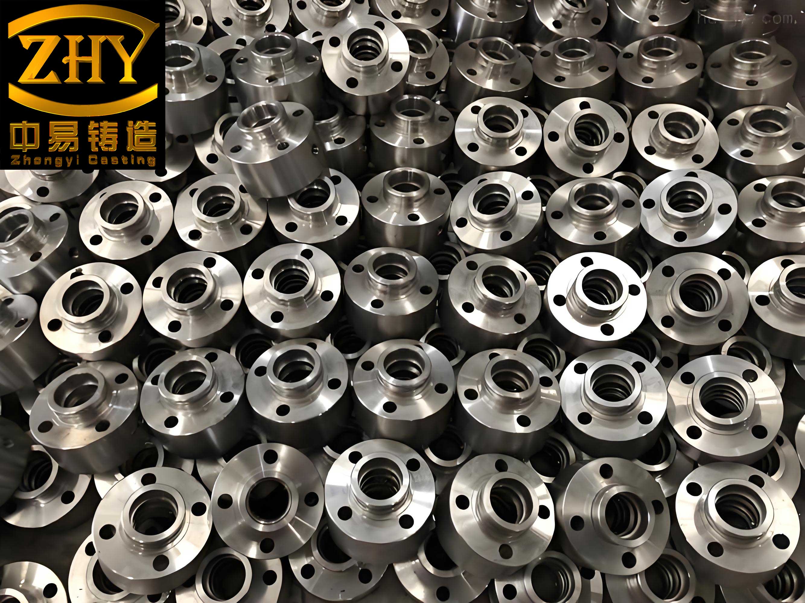
In the development of safety-critical components for commercial and engineering vehicles, the vacuum wheel rim stands out due to its demanding structural and performance requirements. As a key part of the running gear system, its mechanical properties and internal soundness directly influence vehicle safety, comfort, and service life. The component is characterized as a thin-walled, large-diameter casting with a complex outer peripheral groove and numerous ventilation and mounting holes on the web. The specified material is nodular cast iron grade QT450-15, with an average wall thickness of 10–15 mm and a final casting weight of approximately 60 kg.
The conventional production route for standard (non-vacuum) wheel rims often employs green sand molding (e.g., jolt-squeeze or high-pressure lines) or resin sand processes. These methods can adequately address general quality and productivity needs for parts with a simpler external geometry. However, for the vacuum wheel rim featuring its characteristic annular groove, these traditional two-part molding methods become impractical. Producing this groove would necessitate a complex, ring-shaped core, leading to several significant drawbacks: compromised surface finish at the parting line, increased production costs for core materials and labor, reduced operational efficiency, and most critically, the introduction of potential core shift. This misalignment can cause unacceptable variations in wall thickness, a defect that critically undermines the structural integrity and safety performance of the rim. After a comprehensive analysis weighing product structure, safety, surface quality, efficiency, and cost, we determined that the Lost Foam Casting (LFC) process presented a superior technical and economic solution for this application.
The Lost Foam process involves creating a replica of the final part from expandable polystyrene (EPS) foam. This pattern, often assembled with its gating system into a cluster, is coated with a refractory wash, dried, and then embedded in unbonded sand within a flask. The sand is compacted via vibration while a vacuum is applied to the flask. Molten metal is then poured into the foam-filled mold cavity. The heat of the metal rapidly vaporizes and displaces the foam pattern, filling the cavity precisely. The metal solidifies under continued vacuum, producing a casting that replicates the foam pattern’s geometry with high fidelity.
For the vacuum wheel rim in nodular cast iron, the LFC process offers distinct advantages beyond its general benefits of reduced cleaning, improved working environment, and design flexibility. The most compelling advantages for this specific part are:
- Superior Dimensional Accuracy and Wall Thickness Consistency: By eliminating the need for cores and mold parting lines associated with the outer groove, the process ensures exceptional precision in the critical wall sections, directly enhancing product safety.
- Enhanced Surface Finish: The refractory coating applied to the smooth foam pattern results in a superior as-cast surface quality.
- Potential for Near-Net/Net-Shape Casting: The process allows for the direct casting of complex features. We designed the pattern to incorporate the ventilation holes and the valve stem hole as-cast (“net-shape”), eliminating subsequent machining operations for these features. The bolt mounting holes were cast as pre-forms (“near-net-shape”), significantly reducing machining allowance and drill wear, thereby improving machining efficiency.
- Improved Metallurgical Soundness: The application of vacuum during pouring and solidification enhances the filling of thin sections and promotes superior feeding, leading to a denser, more homogeneous microstructure in the nodular cast iron, free from shrinkage porosity.
The primary challenge identified was the potential for distortion of the large, unsupported flange section of the EPS pattern during handling, coating, and sand filling. Our countermeasure was to structurally reinforce this area during the pattern assembly stage.
Process Design and Implementation Strategy
The process development followed a systematic sequence from pattern creation to finished casting. Each stage was optimized for the unique requirements of producing a high-integrity nodular cast iron component.
1. Pattern Production and Assembly
While machined EPS blocks can be used for prototyping, for series production, dedicated aluminum tooling was developed to foam-mold the patterns. To minimize pattern deformation and ensure adequate strength for handling, we specified a controlled EPS bead pre-expansion and molding cycle to achieve a pattern density in the range of 26–32 g/L. This density provides a robust pattern that maintains dimensional stability while ensuring clean, complete pyrolysis during metal pouring without excessive gaseous residue. The foam pattern was produced with all functional holes (ventilation, valve, and bolt pre-forms) integrally molded.
After demolding, patterns were inspected and minor surface imperfections were corrected using a specialized patching compound. The critical anti-distortion measure was then implemented: reinforcing ribs, shaped in a cross or star configuration, were adhesively bonded across the open diameter of the wheel rim’s flange section. This simple addition provided the necessary rigidity.
The gating and feeding system was designed as a top-pouring configuration with multiple ingates to ensure uniform, rapid filling of the thin-walled geometry. A key design parameter was the total cross-sectional area ratio of the gating system, which for nodular cast iron in lost foam often follows a pressurized system principle to maintain a full, turbulent-free sprue. Several small risers/flow-offs were strategically placed at the highest points of the mold (the top flange) to act as atmospheric vents and to collect first-metal slag and coating debris. The complete foam cluster, consisting of the reinforced wheel pattern and the attached gating system, is shown conceptually below.
2. Coating Application and Drying
The refractory coating is a critical interface between the decomposing foam and the solidifying nodular cast iron. We employed a water-based coating with a base of fine silica flour and refractory aggregates, possessing high permeability and good adhesion. The cluster was dipped and subsequently brushed to ensure a uniform, continuous layer over all surfaces, including the complex internal geometries of the holes. The coating thickness is crucial and can be related to the wall thickness of the casting. A general guideline we followed can be expressed as a function to ensure sufficient strength and barrier properties:
$$ \delta_c \approx k \cdot t_{min}^{0.5} $$
where $\delta_c$ is the target coating thickness, $t_{min}$ is the minimum section thickness of the nodular cast iron casting, and $k$ is an empirical constant dependent on the coating composition. For our ~12 mm sections, a dried coating thickness of 0.8–1.2 mm was targeted.
Drying was conducted in a controlled, well-ventilated oven at temperatures not exceeding 55°C to prevent pattern warpage. Drying cycles of 8-10 hours per coat were necessary to remove all moisture thoroughly. Proper drying is non-negotiable, as residual moisture leads to gas defects in the final nodular cast iron casting.
3. Sand Filling, Compaction, and Pouring
We used spherical, calcined ceramic (borg) sand for its excellent flowability and low thermal expansion. The coated cluster was positioned in the flask, and sand was introduced while employing intermittent vibration. Special attention was paid to filling all internal cavities and the annular groove uniformly to achieve consistent and high-density sand packing around the entire pattern. The sand fill level was brought flush with the top of the flask, covered with a plastic film, and a layer of loose sand was placed on top to seal the vacuum.
The flask was connected to the vacuum system, and a negative pressure of 0.04–0.06 MPa was established and maintained. This vacuum serves three vital functions: it rigidizes the unbonded sand mold, accelerates the removal of pyrolysis gases from the mold cavity through the permeable coating and sand, and enhances the metallostatic head, improving feeding. The molten nodular cast iron was treated with a magnesium-ferrosilicon alloy using the sandwich method in a preheated ladle to achieve a fully nodular graphite structure. The treated iron was poured at a temperature of approximately 1,380–1,420°C. The vacuum was maintained for 5–10 minutes post-pour to ensure complete solidification under pressure.
4. Shakeout, Cleaning, and Inspection
After the prescribed cooling time (2–2.5 hours in the flask to below 200°C), the vacuum was released, and the flask was inverted for shakeout. The sand, being unbonded, flows away freely, leaving a clean casting with an attached gating system. The casting was then separated from the gating system via abrasive cutting. Shot blasting was used to remove any residual coating film and reveal the final surface. The as-cast ventilation and valve stem holes required minimal finishing. The bolt holes were machined to their final dimensions with minimal stock removal.
A comprehensive inspection protocol was implemented. Dimensional checks confirmed that the cast-to-size holes and the critical wall thicknesses of the nodular cast iron rim were within specification. Dye-penetrant testing was used to verify the absence of surface defects. Sectioning and microstructural analysis confirmed a fully ferritic matrix with a homogeneous, nodular graphite structure (ASTM Type I, II) and the absence of shrinkage, meeting the QT450-15 grade requirements.
Theoretical Analysis and Process Optimization Considerations
The success of the lost foam process for nodular cast iron hinges on the controlled degradation of the pattern and the subsequent filling and solidification of the metal. We can model key aspects to understand the process window.
Pattern Degradation and Metal Front Velocity: The rate at which the metal advances must be balanced with the rate of foam degradation and gas evacuation. If the metal front velocity ($v_m$) is too high, it can trap liquid pyrolysis products, leading to carbonaceous defects. If too slow, the mold cavity may collapse. An optimal velocity exists, influenced by the pattern density ($\rho_f$), coating permeability, and applied vacuum ($P_v$). A simplified relationship can be considered:
$$ v_m \propto \frac{\sqrt{\Delta P}}{\mu \cdot \rho_f \cdot \delta_c} $$
where $\Delta P$ is the pressure differential driving flow (affected by $P_v$), $\mu$ is the gas viscosity, and $\delta_c$ is coating thickness. For our nodular cast iron rim, the top gating and moderate vacuum provided a $v_m$ that ensured clean displacement without defects.
Solidification and Feeding in Thin-Walled Nodular Cast Iron: Nodular cast iron exhibits a significant graphite expansion phase during eutectic solidification, which can be harnessed for self-feeding. However, in thin sections, this expansion must be managed within the rigid mold. The lost foam mold, under vacuum, provides excellent dimensional stability. The modulus (M) of a section, given by Volume/Surface Area ($M = V/A$), dictates its solidification time ($t_s$) according to Chvorinov’s rule:
$$ t_s = C \cdot M^n $$
where C is a mold constant and n is typically ~2. The thin walls of the rim (low M) solidify very quickly. The key was to ensure that the heavier sections, such as the junction of the rim and the spoke, were properly fed either by direct gating or by exploiting the graphitic expansion in a controlled manner within the rigid mold environment. The vacuum application extended the feeding pressure throughout solidification.
The table below summarizes the key comparative advantages realized by adopting the Lost Foam process for this specific nodular cast iron component versus a hypothetical traditional sand casting approach with cores.
| Parameter | Traditional Sand Casting (with Core) | Lost Foam Casting |
|---|---|---|
| Wall Thickness Control | Susceptible to variation due to core shift. | Excellent consistency; no cores for main geometry. |
| Surface Finish (Groove Area) | Potential for parting line fin and roughness at core prints. | Excellent, smooth finish from coated foam surface. |
| Production of Holes | Requires subsequent drilling/machining. | Vent and valve holes cast net-shape; bolt holes near-net. |
| Process Steps | Molding, core making, core setting, closing, pouring, shakeout, core sand removal, extensive cleaning. | Pattern assembly, coating, sand filling (no binding), pouring, shakeout, minimal cleaning. |
| Material Utilization | Lower due to machining allowance on holes. | Higher for features cast to near-final shape. |
| Internal Soundness | Dependent on gating/risering design; risk of microshrinkage. | Enhanced by vacuum-assisted filling and solidification; very dense structure. |
| Sand System | Bonded sand (clay/resin), requires regeneration/disposal. | Unbonded, reusable sand; minimal waste. |
Conclusion
The development and implementation of the Lost Foam Casting process for the nodular cast iron vacuum wheel rim have proven highly successful. This advanced foundry technique effectively addressed the fundamental challenges posed by the part’s complex geometry, stringent safety requirements, and cost targets. By enabling net-shape casting of critical features, ensuring exceptional dimensional accuracy—particularly uniform wall thickness—and producing a superior surface finish, the LFC process delivered a component that meets all technical specifications. Furthermore, the process leverages the metallurgical benefits of vacuum-assisted pouring and solidification, resulting in a sound, dense microstructure in the nodular cast iron, free from shrinkage and gas-related defects. The use of unbonded sand also aligns with sustainable manufacturing practices by eliminating binder-related emissions and allowing for nearly complete sand reclamation. This project demonstrates that Lost Foam Casting is not merely an alternative but a technologically and economically superior solution for producing high-integrity, complex thin-walled components such as safety-critical wheel rims in nodular cast iron.