
1 Survey analysis
1.1 Current situation and existing problems
Through the investigation of our large-scale casting mold, taking a flywheel shell outer mold mold as an example, its external size is the largest 1240mm×940mm×393mm, cavity depth is 289mm at its deepest point (see Figure 1). On the basis of our existing process equipment, if this kind of mold simply relies on conventional processing methods, it is difficult to process, and it is easy to cause over-cutting of the mold root and reduce the surface roughness. After on-site inspection, it was found that such molds had unevenness in the side wall of the cavity; In the narrow shape, there are many residual phenomena of poor processing; At the root of the deep cavity, there is often corner clearing and overcuting; From the overall point of view of the mold, the appearance quality is not good.
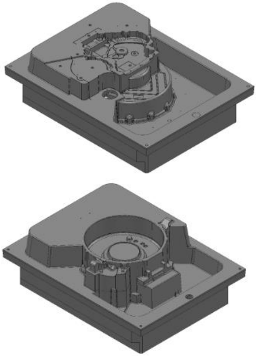
Figure 1 A large flywheel shell mold
1.2 Cause analysis
This kind of mold has the above problems, the reasons are analyzed as follows: 1) The mold shape is complex and the cavity depth is deep. When determining the processing route, the existing process equipment is not fully considered, and the mold structure and mold surface area are not subdivided.
2) When choosing process equipment, the choice is improper. If the tool is selected, the tool performance is not good, the hardness of the cutting edge is not enough, and the spindle rotates There is a slight swing at the far end of the tool during rotation, the edge wears quickly, and there is a break when the multi-layer tool path is connected.
3) The selection of process parameters is unreasonable. For example, when selecting shallow and steep critical angles, the angle is selected too small, and the speed is set with When the feed speed is proportioned, the ratio is unreasonable, etc.
4) Poor process control. During the entire mold processing process, technicians and quality control personnel did not follow up in time, and the operator paid little attention to the use of tools.
1.3 Countermeasures
Through the investigation of the current situation and the analysis of the causes, the problems that need to be solved are determined, and the technical measures are focused on and the measures are formulated as follows:
1) Change the mold structure Based on the irrationality of the mold structure, fully consider the ease of mold processing, and clamp in the existing Based on the length of the tool, the monolithic type is changed to the inlay type, and it is machined separately.
2) Choose process equipment with better performance The fixture must be leveled before mold clamping, and ensure that the surface is clean to ensure mold clamping of smoothness. When selecting tools, choose tools with better performance as much as possible, if the hardness of the processed parts is HRC30~40, you can choose tools with higher hardness than the workpiece, and the cutting edge must be coated. When clamping the tool, it must be clamped in place to prevent “dropping the tool” during machining.
3) Choose reasonable process parameters The ratio of tool speed and feed speed should be set reasonably, and when designing the tool path trajectory point, the one-time tool clamping length should be fully considered to avoid the break on the machining surface when connecting the tool. If some small knives need to be layered, they can be set by parameter grading and adopt the “short, fast, long and slow” advance Set the principle of speed, and set the margin setting principle of “large, less, small, more” to avoid the occurrence of overgouging. Due to the long tool clamping, considering the factor of extrusion of the tool by the processing load, other parameters can be appropriately refined when setting, so as to effectively improve the surface quality of the mold.
4) Personnel management The operator should pay attention to the use of process equipment at any time, and the tool wear should be replaced in time, and there should be abnormalities when processing. Technicians should follow up in time, check from time to time, and pay close attention to the operation of the program.
2 Process implementation
2.1 Processing process analysis
These molds are large and easier to machine when converted to inlay (see Figure 2), but due to the post-machining process The order to carry out the installation and connection of the upper and lower parts, the fitting part is not allowed to have a break, so the setting of parameters and the selection of tools are required to be reasonable and scientific, improper parameter selection will cause the radial jump of the tool Dynamic, affect the surface quality of the mold.
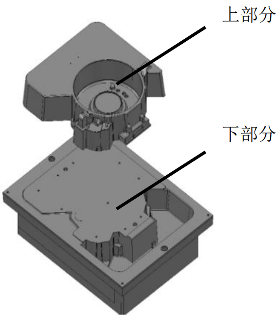
Figure 2 Mosaic structure
For the upper part, due to the rigidity of the machine tool, tooling accuracy, tool runout, etc., under unreasonable parameter settings, the residual amount of the surface of the body will be increased and the margin will be exceeded, and the upper and lower parts of the residual meat will inevitably appear when the upper and lower connection assembly, thereby increasing the workload of fitter research and distribution, so the remaining amount can be set when the margin is set is zero or negative values are set within the range of process requirements. For the lower half, because the cavity height exceeds the clamping length of the existing finishing tool, it is not considered to use a ball head knife for machining, but a small rounded corner, relatively stable tip end milling cutter for finishing milling, the margin setting can be appropriately more than the upper half, controlled within 0.05mm, which can effectively avoid the formation of grooves in the fitting part due to the tool clamping too long tool tip bullet knife, which is more conducive to fitter research and matching.
2.2 Analysis of processing strategy
The processing of a pair of molds can be divided into several steps, including first rough processing, second rough processing, semi-finishing processing, finishing and root cleaning, each step
It can be divided into multiple tools, each of which uses a different strategy. Its commonly used processing strategies include offset area removal model, residual area clear model, contour finishing, three-dimensional offset processing, parallel finishing, offset flat surface finishing, corner clearing finishing, parallel flat surface finishing, etc., and different strategies are selected according to different needs. This paper focuses on the exploration of more suitable process methods for processing large casting molds, so when selecting strategies, we start from innovation to improve the processing quality of the mold surface as the ultimate goal, so some strategies in the selection of strategies adopt strategies that are only used in multi-axis, and try to superimpose between strategies to improve the processing efficiency of molds.
2.3 Tool selection
For the selected tool for the first rough machining, from the consideration of machining efficiency, a large-diameter tool should be selected; Second, the diameter of the tool is reduced sequentially, and the minimum value is smaller than the diameter of the selected tool for finishing; After finishing, small tools are selected in turn to clean and finish them; Considering the model features, due to the large parting surface, It belongs to a flat surface, so a large fillet flat bottom knife can be used for plane machining, so as to improve the processing accuracy and processing efficiency; The local root has no fillet characteristics, and can be used for contour machining with a flat-bottomed knife. knife With options for H50R6, H32R6, H25R5, S10R5,S8R4, S6R3, S4R2, E6, E16, tool some parameters The settings are shown in Table 1.
Table 1 Table of tool parameters
| 刀具 名称 | 直径 | 刀尖 半径 | 长 度 | 顶部 直径 | 底部 直径 | 长 度 | 顶部 直径 | 底部 直径 | 长度 |
| H50R6 | 50 | 6 | 200 | 50 | 50 | 300 | 105 | 105 | 80 |
| H32R6 | 32 | 6 | 169 | 32 | 32 | 300 | 105 | 105 | 80 |
| H25R5 | 25 | 5 | 153 | 25 | 25 | 200 | 105 | 105 | 80 |
| S10R5 | 10 | 5 | 120 | 10 | 10 | 150 | 45 | 45 | 100 |
| S8R4 | 8 | 4 | 102 | 8 | 8 | 150 | 45 | 45 | 100 |
| S6R3 | 6 | 3 | 62 | 6 | 6 | 100 | 45 | 45 | 100 |
| S4R2 | 4 | 2 | 10 | 4 | 4 | 50 | 45 | 45 | 100 |
| D6 | 6 | – | 12 | 6 | 6 | 100 | 45 | 45 | 100 |
| D16 | 16 | – | 153 | 16 | 16 | 200 | 105 | 105 | 80 |
2.4 Processing technology formulation and parameter setting
H50R6 fillet end mills were selected for integral roughing of the model; Choose the H25R5 tip fillet end mill
The model is re-roughed and partially finished; The ball milling cutter of S10R5 is selected to open the model again on the basis of the above secondary roughing; The ball milling cutter selected S8R4 continues to process the residual processing of the narrow part of the inner cavity of the model on the basis of the above machining, so that the internal cavity margin of the model is as uniform as possible
Homogeneous so that profile quality and precision can be ensured during finishing. Precision and efficiency should be considered when selecting tools for finishing, and a balance point should be found as much as possible, and larger diameter tools should be selected from the consideration of processing efficiency. However, considering that the minimum fillet of the shape part of the inner cavity of the model is R2, in order to avoid some overcut or residue due to the inconsistency of the margin before and after in the future, which will affect the quality of the profile, the S4R2 ball nose knife that matches the minimum R of the shape part is selected for local finishing, and the ball head of S6R3 and S4R2 is selected for the residue of some mating parts The milling cutter is finished with clear corners, and the D6 flat bottom knife is selected without rounded corners at the root.
2.5 Pass design
2.5.1 Roughing Passes
The first roughing uses an H50R6 tool with parameter settings shown in Figure 3. By calculating pairs for the settings of different parameters Ratio, on the basis of not affecting the calculation efficiency, the smaller the tolerance value, the better, from the experience accumulated in the past, the tolerance value does not need to be set too small when roughing, can be set 0.05mm ~ 0.1mm that is Can. In the direction of the tool rotation milling material, as much as possible to choose climb milling, mainly because the distance of the cutter teeth on the workpiece during climb milling is shorter than that of conventional milling, so under the same cutting conditions,Climb milling reduces tool wear more than conventional milling. However, climb milling is not easy to process workpieces with hard skin, considering the material of the flywheel shell, so the processing direction is more suitable for climb milling.
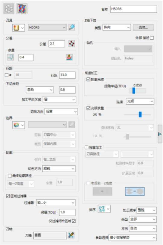
Figure 3 Model Area Cleanup parameter setting
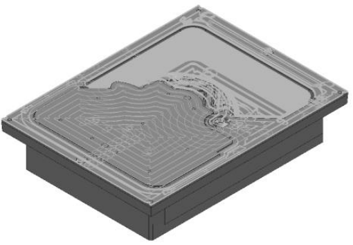
In terms of cutting in and out, and connection, the “skimming distance” was set to 15mm and the “down-cutting distance” was 6mm, which greatly affected the problem of excessive invalid cutting distance during the machining process Processing efficiency, by changing the parameters, reducing the skimming distance and cutting height, so that the processing efficiency is greatly improved. In the oblique cut selection, the previous rough machining cut is oblique, although the safety is high, but there is also a problem that affects the processing efficiency, through multiple settings, calculations, comparisons, the final left oblique angle is set to “3”, “along” is set to “circle”, “circle diameter” is set to “0.5”, oblique height The degree is set to “1”, the cut angle is changed to 90°, the radius of “horizontal arc” is set to “2”, the “long and short cut-off value” is set to “50”, “short” is set to “on the surface”, “long” is set to “skimm”, “default” is set to “relative”, etc., after a series of “cut-in” and “cut-out” parameters are optimized for settings, the final path trajectory is shown in Figure 4 shown.
2.5.2 Finishing Passes
(1) Contour finishing After analyzing the model, the minimum root R of the shape part is R2, considering that most of its root fillets are R5, In order to improve efficiency while ensuring the quality of the surface, the profile part is finished with a ball nose knife from S10R5. The parameter settings have also been partially refined based on previous experience. The upper and lower half parameter settings are shown in Figure 5 and Figure 6. When setting the Cut In and Cut Out, set the Z Height to 5, the Cut Down Distance to 2, and the Relative Distance to Cutter Pathpoints, Cut In, and Cut Out are all set to None, and Short is connected Set to “On the surface”, the path after calculation is extremely refreshing, with a total of more than 100 lifts, of which only two parallel finishing tools are raised, which is a great improvement over the previous machining efficiency.
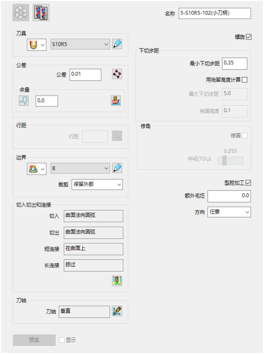
Figure 5 Upper finishing parameter settings
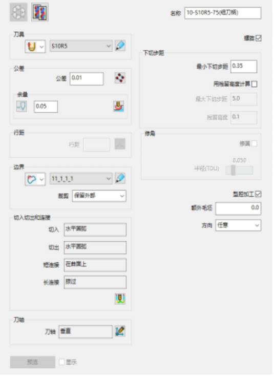
Figure 6 Lower finishing parameter settings
(2) Flat surface finishing There are six flat surfaces with a large outer mold of the flywheel shell, and if the plane is simply milled with a flat bottomer, it is qualified The amount can be guaranteed, but due to the small row spacing setting, low machining efficiency, and greater wear on the tool, resulting in an increase in processing costs, after comprehensive consideration, the final use of a knife with a diameter of 25 and a fillet of 5 Sharp fillet end mill for machining, its row spacing setting can not be too large and too small, generally according to (D-R)/2 setting or slightly larger, but not greater than D-2R, where D is the tool diameter, R is the tool fillet.
2.5.3 Corner clearing toolpaths
Since the corners are cleared with a tool with a smaller diameter, the risk of broken tools and root gouges should be paid attention to when setting parameters. The side wall adopts the method of contour finishing, the root can be three-dimensional bias, can also be carried out by pen and stitching, this programming uses the strategy of combining contour and three-dimensional bias, which
It is better in terms of safety and efficiency. For the narrow part of the part, if necessary, use a knife with a small diameter to open the thick again, so as not to cause the knife to break when cleaning the root.
3 Simulation
Simulation is an essential part of the CAM process, as shown in Figure 7. It is a process that simulates cutting and is based on All the above parameters are set to calculate the final state of the tool path, and the simulation can save the cost of the actual trial cutting processing of the machine tool. The simulation process is also the process of checking cutting conditions such as gouging, collision, climb milling (conventional milling) and machining quality, and it is important to perform simulation review after all settings are completed.

Figure 7 ViewMILL simulation effect
4 Effect evaluation
Through the exploration of the flywheel shell outer mold processing technology, the surface quality and production efficiency of the processed mold have been greatly improved, and the expected purpose has been achieved, which is mainly reflected in:
1) The side wall of the cavity is smooth, the upper part and the lower part of the fitting part do not have a break, the connection is good, and the surface quality of the mold is guaranteed
It also reduces the amount of research and distribution of fitters and reduces costs, as shown in Figure 8.
2) In the lower part of the cavity sidewall, no overcut phenomenon was found, no wavy ripple phenomenon was found on the surface, and the overall excessive was relatively smooth.
The overall appearance of the mold is good.
3) The upper part of the narrow part, no residue, all processed in place, no knife path residue in the large plane, flat surface.
4) Improve processing efficiency. Due to the optimization of the processing technology, parameters, etc., the implementation process is also followed up in a timely manner, assembly
The process was also shortened from the previous two days to one day, achieving the expected effect.

Figure 8 After the upper and lower parts are assembled
5 Summary
Through this exploration of large-scale casting mold processing methods, he deepened his own work in the processing process of large-scale casting molds Awareness of technological innovation, cost reduction and quality improvement. The factors affecting the efficiency and quality of a pair of mold processing are many, not only can simply consider the setting of process parameters and the use of certain plug-in programs, but also fully consider the mold structure, mold materials, equipment performance, operator skill level and others The influence of process factors. Therefore, strictly control all links in the mold manufacturing process in order to truly control the cost of mold manufacturing, improve the quality of mold manufacturing, improve the efficiency of mold processing, and thus shorten the mold
Delivery time.