
I approach the ductile iron casting of a water-jacket exhaust manifold as a system problem rather than as a single foundry operation. The part combines a hot exhaust gas chamber, a surrounding water chamber, thin walls, long and slender cores, several isolated thermal nodes, and a demanding pressure-tightness expectation. In my experience, a successful ductile iron casting process for this family of components depends on the simultaneous control of gating, feeding, core strength, core venting, mold permeability, pouring discipline, and cleaning access. Every decision in the foundry must support balanced solidification, because the manifold cannot tolerate uncontrolled shrinkage, core fracture, sand burn-on, flash, or incomplete filling. The following discussion describes the first-person production logic I use for a six-cylinder marine-type water-jacket exhaust manifold made from QT400-15 ductile iron casting.
The product envelope is approximately 1135 mm long, 186 mm wide, and 178 mm high, with a finished weight near 24.6 kg. The gas chamber collects exhaust pulses from six cylinders, while the water jacket wraps around the gas passages to reduce wall temperature, external radiation, and exhaust temperature. The wall thickness of both the gas chamber and the water chamber is generally 6 mm. The casting includes six intake flanges, one outlet flange, one water inlet, one water outlet, one EGR flange, six process holes, and six bolt bosses. These features create a geometry that is not naturally self-feeding. The isolated thermal nodes are numerous, and the thin walls cool quickly while adjacent flanges and bosses remain liquid longer. In ductile iron casting, this difference in cooling rate can produce shrinkage porosity, misruns, cold shuts, and expansion defects if the process window is not tightly defined.
I select QT400-15 as the material because it offers a favorable combination of tensile strength, elongation, ferrite matrix, and thermal fatigue resistance. For this ductile iron casting, I target a spheroidization rate of at least 80%, a ferrite content of at least 90%, and a graphite morphology that remains stable after the final pouring stage. The mechanical property target is not merely a room-temperature certificate. It is a process constraint that influences carbon equivalent, magnesium and rare-earth addition, inoculation practice, cooling rate, and riser behavior. The chemical composition must be adjusted so that graphite expansion can be used for self-feeding without creating excessive dross, slag, or carbides.
| Item | Target or Requirement | Process Consequence |
|---|---|---|
| Material | QT400-15 ductile iron casting | Ferritic matrix, high elongation, thermal fatigue resistance |
| Spheroidization rate | ≥80% | Requires controlled Mg and Re addition |
| Ferrite content | ≥90% | Limits pearlite and carbide formation |
| Wall thickness | 5 to 6 mm | Fast cooling, high risk of misrun and cold shut |
| Overall length | About 1135 mm | Long melt path and thermal gradient control |
| Weight | About 24.6 kg | Moderate pouring weight with high surface-area-to-volume ratio |
| Critical features | Six intake flanges, outlet flange, EGR flange, water inlet and outlet | Multiple isolated hot spots and feeding points |
| Process holes | Six holes for core location, venting, and cleaning | Essential for water-jacket core stability and internal cleaning |
I use a green sand molding process with two boxes and a horizontal parting line through the middle of the gas chamber. The intake flanges are placed vertically. This orientation supports core location and reduces the tendency for long water-jacket cores to shift during closing. Because the order quantity is moderate and the product is large, I use a jolt-squeeze molding machine and a flask size of 1500 mm × 800 mm × 300 mm. One casting is produced per mold. The lower box is supported by a shell core, while the internal cavities are formed by an air chamber core and upper and lower water-jacket cores. The mold cavity therefore consists of the upper green sand, the lower green sand, the lower shell core, the air chamber core, and the two water-jacket cores.
My core strategy is based on a simple principle: every core must be strong enough to survive handling, locating, pouring, and shakeout, but it must also vent gas freely and collapse cleanly. The water-jacket core is the most difficult because it is thin, long, and supported at relatively few points. I link the ends of the water-jacket core with cross ribs to form a stronger assembly. One end forms the intake flange holes, and the other end forms the process holes. The cross ribs reduce bending and torsion, improve locating reliability, and help prevent wall thinning caused by core deformation. The air chamber core is made hollow with vent needles in the core box so that gas can escape through the core print. The lower shell core provides a stable base for the core package and controls the lower surface of the water jacket.
| Core or Mold Element | Primary Function | Critical Control |
|---|---|---|
| Lower shell core | Forms lower shell surface and supports core package | Dimensional stability and clean location |
| Air chamber core | Forms exhaust gas passages | Hollow venting, core print strength, no deformation |
| Lower water-jacket core | Forms lower half of water cavity | Thickness, vent slots, cross-rib support |
| Upper water-jacket core | Forms upper half of water cavity | Assembly clearance, anti-flash gasket, no crush |
| Upper green sand | Forms top exterior and vent path | Hardness, permeability, drilled vent holes |
| Lower green sand | Forms bottom exterior and core seat | Sand cleaning, core support, no loose sand |
I define the core-to-core and core-to-mold clearances carefully because the ductile iron casting has thin walls. If the clearance is too small, core deformation or sand expansion can crush the core and create a thin wall or sand inclusion. If the clearance is too large, metal penetration, flash, or dimensional deviation can occur. For the lower shell core and the lower mold, I increase the clearance to about 1 mm to avoid interference and falling sand. For the water-jacket cores, I use about 1.5 mm at the joint where the upper and lower cores meet. This larger gap prevents the cores from being pressed together during mold closing, allows room for adhesive, and reduces the risk of core fracture. The matching clearance between cores and the green sand is generally 0.3 to 0.5 mm, the draft angle is 3 to 5 degrees, the process positive allowance is 0.3 to 0.5 mm, and the parting negative allowance is 0.5 mm.
I express the pattern allowance relationship in a general form. The pattern dimension is increased by a shrinkage factor and adjusted by process allowances:
$$L_{\text{pattern}} = L_{\text{casting}} \left(1 + \epsilon_s\right) + a_p – a_n$$
where \(L_{\text{pattern}}\) is the pattern dimension, \(L_{\text{casting}}\) is the required casting dimension, \(\epsilon_s\) is the solidification shrinkage factor, \(a_p\) is the process positive allowance, and \(a_n\) is the parting negative allowance. For this ductile iron casting, the shrinkage factor is not applied uniformly because graphite expansion compensates part of the liquid and solidification contraction. I therefore divide the part into feeding zones and apply local allowances rather than a single global shrinkage value.
The gating system is a middle pouring system. I calculate the choke area with the Osann relationship and then select a semi-closed gating ratio:
$$S_{\text{sprue}} : S_{\text{runner}} : \sum S_{\text{ingate}} = 1.2 : 1.4 : 1$$
This ratio allows the runner to remain full and to act as a slag trap. The ingates are short, thin, and wide. A short ingate reduces friction loss; a thin ingate freezes early and prevents iron from returning from the mold during graphite expansion; a wide ingate distributes metal over a larger area and reduces local overheating. I also increase the runner length and cross section as much as the layout permits. A long runner gives inclusions time to float into the runner top, while a large runner cross section keeps the temperature field more uniform along the long manifold.
| Gating Parameter | Design Choice | Reason |
|---|---|---|
| Pouring position | Middle pouring | Balances filling distance and temperature loss |
| Gating ratio | Sprue : runner : total ingate = 1.2 : 1.4 : 1 | Semi-closed system with slag-trapping runner |
| Ingate shape | Short, thin, wide | Fast fill, early freeze, expansion self-feeding |
| Runner function | Full runner and slag trap | Inclusion flotation and uniform temperature |
| Choke calculation | Osann equation | Controlled filling time and velocity |
| Pouring basin | Full sprue during pour | Prevents air entrainment and slag entry |
The Osann calculation can be written in a practical form. The choke area is related to the pouring weight, pouring time, density, and effective head:
$$A_c = \frac{W}{\rho t \mu \sqrt{2gH}}$$
where \(A_c\) is the choke area, \(W\) is the pouring weight, \(\rho\) is the liquid iron density, \(t\) is the pouring time, \(\mu\) is the discharge coefficient, \(g\) is gravitational acceleration, and \(H\) is the effective metallostatic head. I use this equation as a starting point and then adjust the result for the actual molding line, ladle height, and pouring temperature. For a thin-wall ductile iron casting, the calculated area must not be so small that the fill time becomes excessive, but it must not be so large that the gating system becomes turbulent. I prefer a stable, slightly pressurized flow that keeps the sprue full and minimizes air entrainment.
Feeding is designed with balanced solidification technology. I place hot-side risers at the intake flanges, bolt bosses, and outlet flange. The iron enters the casting through the risers, so the risers remain hot and feed the adjacent thermal nodes. I use a riser neck that is thin, wide, short, and inclined. Thin means the neck freezes at the end of feeding; wide means the neck has enough cross section to pass liquid iron; short means the flow path is not restricted; inclined means the feeding direction is favorable. Opposite the hot risers, I place two cold risers to balance the temperature field and reduce the thermal gradient along the length. At locations that are difficult to feed with risers, I use shaped chills to increase the local cooling rate and promote directional solidification toward the riser.
The modulus method is useful for comparing feeding demand and feeding capacity:
$$M = \frac{V}{A}$$
where \(M\) is the modulus, \(V\) is the volume of the section, and \(A\) is the heat-transfer surface area. The solidification time can be approximated by Chvorinov’s rule:
$$t_s = K M^n$$
where \(t_s\) is the solidification time, \(K\) is a mold constant, and \(n\) is an exponent close to 2 for many casting conditions. For balanced solidification, I want the riser to solidify after the feeding zone, but I also want the graphite expansion to compensate the remaining contraction. The expansion behavior can be summarized as:
$$\epsilon_{\text{total}} = \epsilon_{\text{liquid}} + \epsilon_{\text{solidification}} + \epsilon_{\text{graphite}}$$
If graphite expansion is fully utilized, the feeding requirement is reduced. However, expansion is only useful when the mold is rigid enough and the ingates freeze at the correct time. That is why I use a semi-closed gating system, short-thin-wide ingates, and strong mold compaction. The mold must resist expansion pressure rather than allowing the wall to move outward. I estimate the expansion pressure qualitatively as:
$$P_{\text{exp}} = E \epsilon_T$$
where \(P_{\text{exp}}\) is the expansion pressure, \(E\) is the elastic modulus of the mold or core assembly, and \(\epsilon_T\) is the thermal strain. In practice, the mold hardness, sand compaction, core rigidity, and clamping force determine whether this pressure helps feeding or creates mold wall movement and shrinkage defects.
| Feeding Feature | Location | Function |
|---|---|---|
| Hot-side riser | Intake flanges | Feeds isolated flange nodes |
| Hot-side riser | Bolt bosses | Compensates local thermal mass |
| Hot-side riser | Outlet flange | Feeds final heavy section |
| Cold riser | Opposite hot risers | Balances temperature field |
| Shaped chill | Local difficult-to-feed areas | Increases cooling rate and directionality |
| Riser neck | Between riser and casting | Thin, wide, short, inclined for feeding and freeze-off |
Melting is controlled to produce a clean, well-inoculated ductile iron casting. I use a medium-frequency induction furnace. The nodularizer is a heavy rare-earth magnesium ferrosilicon alloy, FeSiMg7Re3, added at 1.0% to 1.2%. The pre-furnace inoculant is FeSi75-C at 0.3% to 0.5%. The treatment process is as follows: I place the nodularizer in the pocket of the ladle, cover it with part of the inoculant, compact it with a flat ram, cover it with dry ductile iron chips, and add perlite. The tapping temperature is at least 1540 °C. I avoid directing the iron stream onto the nodularizer. When two-thirds of the iron has been tapped, I stop the tap, add the secondary inoculant during the middle and late stages of the reaction, and then continue tapping to the required weight. The reaction time is preferably 45 to 100 s. After the reaction, I add a slag remover, skim the surface, cover the iron with slag remover, and prepare for pouring.
| Element or Condition | Before Spheroidization | After Spheroidization |
|---|---|---|
| C | 3.79% | 3.61% |
| Si | 1.92% | 2.84% |
| Mn | 0.192% | 0.187% |
| P | 0.029% | 0.029% |
| S | 0.011% | 0.007% |
| Re | Not added | 0.013% |
| Mg | Not added | 0.038% |
For the ductile iron casting, the carbon equivalent is kept within a range that promotes graphite expansion and ferrite formation. A practical carbon equivalent expression is:
$$CE = C + \frac{Si}{3} + \frac{P}{3}$$
Using the final composition, the carbon equivalent is approximately:
$$CE = 3.61 + \frac{2.84}{3} + \frac{0.029}{3} \approx 4.57$$
This value supports good fluidity and graphite expansion while remaining within the range I prefer for thin-wall QT400-15. I also control magnesium and rare earths because excessive residual magnesium can increase dross and shrinkage tendency, while insufficient magnesium reduces spheroidization. The residual Mg of about 0.038% and Re of about 0.013% provide a stable nodularizing effect when combined with proper inoculation and cooling rate.
Core making is one of the most important controls for this ductile iron casting. I use a hot-box process with high-strength, low-gas coated sand. The sand grain size is 50/70 mesh. The base sand is silica sand with SiO2 content of at least 85%. The coarse grain size improves permeability and venting, which is critical because the water-jacket core has a large surface area and generates gas during pouring. At the same time, the coated sand must provide enough hot and cold strength to resist core deformation, core breakage, and wall thinning. I specify the coated sand properties within narrow ranges.
| Coated Sand Property | Target Value | Reason |
|---|---|---|
| Grain size | 50 to 70 mesh | High permeability and good surface finish balance |
| Hot tensile strength | 2.2 to 2.3 MPa | Resists core breakage during pouring |
| Cold tensile strength | 4.8 to 5.2 MPa | Survives handling and assembly |
| Hot bend strength | ≥2.5 MPa | Maintains shape under thermal load |
| Cold bend strength | 7.0 to 8.0 MPa | Provides handling rigidity |
| Gas evolution | ≤13 mL/g | Reduces blowholes, scabs, and back pressure |
| Loss on ignition | ≤3.0% | Controls gas-forming volatiles |
The air chamber core is made hollow with vent needles. This lowers core weight, reduces gas evolution, and allows gas to escape through the core print. The water-jacket cores have vent grooves on the parting surfaces between the upper and lower cores. These grooves give the gas a defined path to the process holes and core prints. The core package is assembled on a special fixture. Adhesive is applied at the joints, and the assembly is cured before being lowered into the mold. The assembled core package has enough rigidity to be handled as one unit, which reduces the risk of individual core movement and improves dimensional repeatability.
To prevent flash at the water-jacket parting surface, I apply an anti-flash gasket at the joint between the upper and lower water-jacket cores. This gasket blocks liquid iron from entering the joint and forming a mid-wall fin. Such a fin would reduce water flow, increase cleaning difficulty, and create a local hot spot during service. The gasket also compensates minor core mismatch and protects the joint from metal penetration. I consider this detail essential in a ductile iron casting with a long, narrow water passage.
| Core Assembly Control | Value or Method | Purpose |
|---|---|---|
| Core-to-mold clearance | 0.3 to 0.5 mm | Controlled location without sand crush |
| Lower shell core clearance | About 1 mm | Prevents interference and falling sand |
| Water-jacket joint clearance | About 1.5 mm | Prevents core crushing and allows adhesive |
| Draft angle | 3 to 5 degrees | Clean core removal and dimensional stability |
| Process positive allowance | 0.3 to 0.5 mm | Compensates core and mold variation |
| Parting negative allowance | 0.5 mm | Controls parting-line mismatch |
| Assembly fixture | Dedicated tooling | Repeatable core package geometry |
| Adhesive cure | Controlled time and temperature | Strong joints without distortion |
After core assembly, I coat the cores with a refractory wash. Because the coated sand is coarse, the core surface is relatively rough. The wash improves surface finish and reduces metal penetration. I place the core vertically during coating so that the wash drains uniformly. The infiltration depth is controlled to less than 1 mm. If the wash penetrates too deeply, the core retains more gas and the coating layer can spall during pouring, causing scabs, peeling, and back pressure defects. The coating must be dry before the core is placed in the mold.
Molding is performed with green sand and a jolt-squeeze machine. I use high-quality coal dust and bentonite. The molding sand properties are controlled to provide strength, permeability, and collapse behavior. The target permeability is at least 90. Moisture is 4.5% to 5.0%. The compactability is 40% to 50%. The clay content is 16% to 18%. The wet compressive strength is at least 0.1 MPa. These values support good mold strength while allowing gas to escape. The upper mold hardness is controlled near 80 on the C-type hardness tester. I also drill vent holes at every core print in the upper mold. These vent holes allow gas from the cores and mold to escape freely during pouring.
| Molding Sand Property | Target Value | Effect on Ductile Iron Casting |
|---|---|---|
| Permeability | ≥90 | Reduces blowholes and back pressure |
| Moisture | 4.5% to 5.0% | Balances strength and gas evolution |
| Compactability | 40% to 50% | Provides mold density and formability |
| Clay content | 16% to 18% | Controls green strength and durability |
| Wet compressive strength | ≥0.1 MPa | Resists erosion and expansion pressure |
| Upper mold hardness | About 80 | Good compaction without excessive gas entrapment |
Before closing, I clean the lower mold thoroughly. The core package is heavy and large, so any loose sand left in the mold can be washed into the cavity and form sand inclusions. I remove all loose sand from the core seats, parting line, and vent paths. The assembled core package is lowered into the lower box as a single unit. I then close the upper box and clamp the two boxes with box clamps. The mold is ready for pouring.
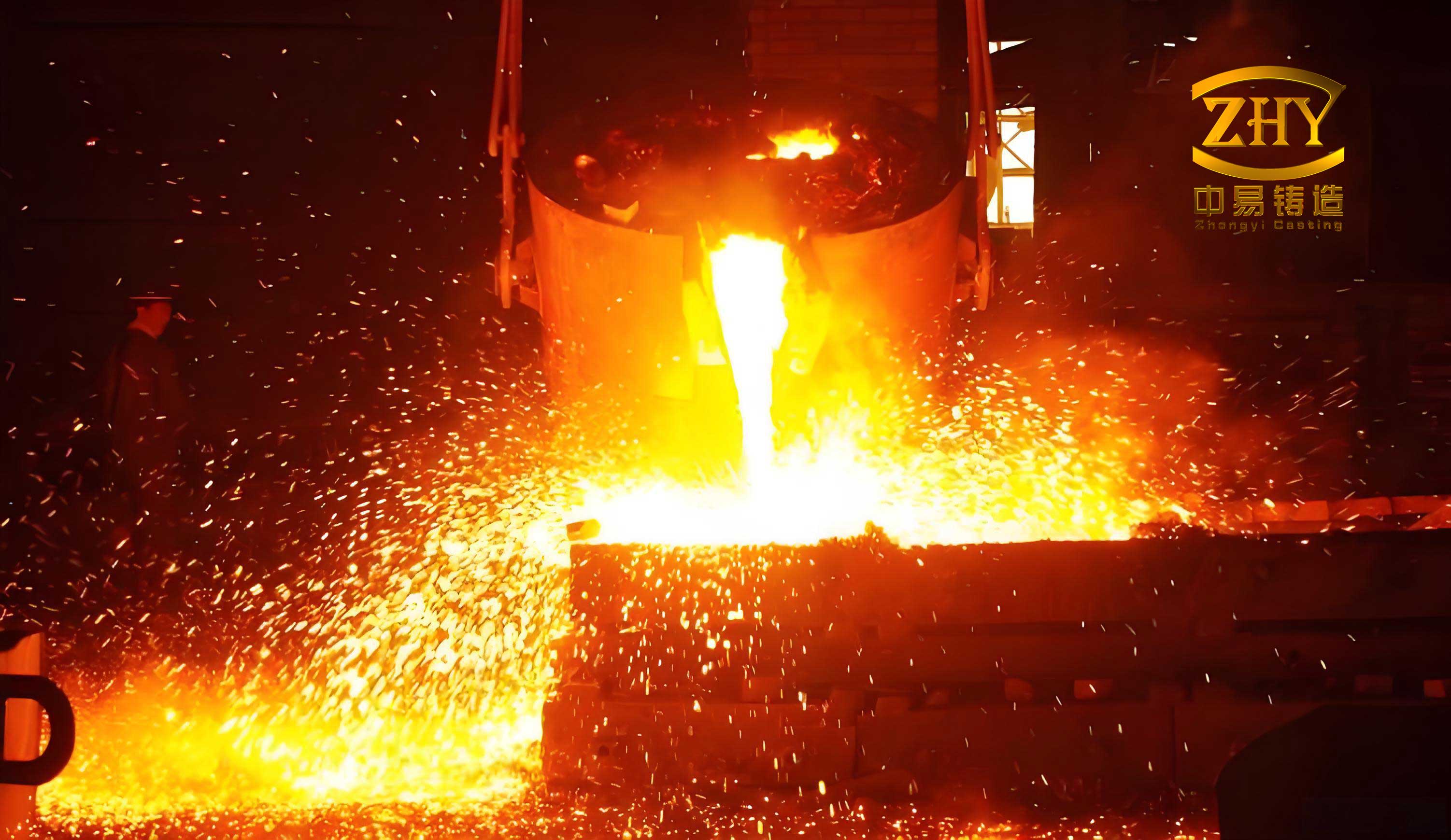
Pouring is a time-critical step. I target a pouring temperature of at least 1380 °C. The entire process from the start of iron treatment to the last mold must be completed within 15 minutes. The pouring time for the casting is kept below 10 minutes. During pouring, the sprue must remain full. I use stream inoculation with 0.1% to 0.15% of a long-acting inoculant, FYJ-1a, to prevent inoculation fade and to promote graphite nucleation throughout the pour. The iron stream must not be interrupted because an interrupted stream can draw air and slag into the mold. I also maintain a steady pouring rate so that the metal front rises smoothly in the thin water-jacket and gas-chamber sections.
| Pouring Parameter | Target | Reason |
|---|---|---|
| Pouring temperature | ≥1380 °C | Ensures fluidity in 5 to 6 mm walls |
| Treatment-to-pour time | ≤15 min | Limits inoculation fade and magnesium loss |
| Pouring time | ≤10 min | Controls filling and temperature loss |
| Stream inoculation | 0.1% to 0.15% FYJ-1a | Maintains nucleation and ferrite stability |
| Sprue condition | Full during pour | Prevents air and slag entrainment |
| Pouring continuity | No interruption | Avoids cold shut and reoxidation |
After pouring, the castings are allowed to cool in the mold. Shakeout must be controlled because the ductile iron casting has thin walls and long cores. If the casting is shaken out too early, residual stresses and distortion can occur. After shakeout, the casting still requires careful cleaning. The main cleaning difficulty is the water jacket. The water passage is narrow, and the internal space is small. Sand, fins, and burned-on material can restrict water flow or create local hot spots in service. I use an endoscope to inspect the gas chamber and water chamber after cleaning. For the water jacket, I use a nozzle to shot blast the internal cavity, and then I use an air gun to blow out the steel shot. For local dead corners where burrs or sand burn-on remain, I use a high-pressure water jet for targeted cleaning. If a burr or burned-on sand cannot be removed by shot blasting, I heat the casting to 600 °C, hold for 1 hour, cool in air, and then vibrate it on a shakeout machine for 10 minutes. This thermal and mechanical action usually removes the remaining material.
| Cleaning Step | Method | Control Point |
|---|---|---|
| Initial shakeout | Controlled vibration | Avoid distortion and core breakage |
| External cleaning | Shot blasting | Remove sand and scale |
| Water-jacket cleaning | Internal shot blast nozzle | Reach narrow passages |
| Debris removal | Air gun blow-out | Remove steel shot and loose material |
| Dead-corner cleaning | High-pressure water jet | Remove local burrs and burn-on |
| Stubborn residue | Heat to 600 °C for 1 h, air cool, vibrate 10 min | Loosen and remove residual sand |
| Internal inspection | Endoscope | Verify gas and water passage cleanliness |
The trial production and subsequent process refinement showed that the ductile iron casting can meet the technical requirements when the process windows are respected. The microstructure of the manifold wall was examined. The spheroidization level was grade 2, the spheroidization rate was 92%, and the graphite size was grade 7. The ferrite content was at least 94%. The mechanical properties from the attached test block were 475 MPa tensile strength, 357 MPa yield strength, 21% elongation, and 168 HB hardness. These values satisfy the QT400-15 requirements and provide a safe margin for the intended marine and explosion-proof engine applications.
| Property | Measured Result | Requirement or Target |
|---|---|---|
| Spheroidization level | Grade 2 | Good nodularity |
| Spheroidization rate | 92% | ≥80% |
| Graphite size | Grade 7 | Fine and uniform |
| Ferrite content | ≥94% | ≥90% |
| Tensile strength | 475 MPa | QT400-15 minimum |
| Yield strength | 357 MPa | Acceptable for design |
| Elongation | 21% | High ductility |
| Hardness | 168 HB | Within specification |
During early trials, the water-jacket exhaust manifold exhibited several defects: wall thinning, sand holes, inclusions, back pressure or scab defects, peeling, shrinkage porosity, and mid-wall fins. I treated each defect as a process signal. Wall thinning was linked to core deformation, insufficient core strength, and incorrect core clearances. Sand holes were linked to loose sand in the mold and core seat contamination. Inclusions were linked to an unstable gating system, insufficient slag trapping, and turbulence during pouring. Back pressure and peeling were linked to excessive core gas, insufficient venting, and coating infiltration that was too deep. Shrinkage porosity was linked to unbalanced feeding, riser neck design, and local hot spots. Mid-wall fins were linked to core joint gaps and metal penetration between the upper and lower water-jacket cores.
| Defect | Main Cause | Control Measure |
|---|---|---|
| Wall thinning | Core deformation or core crush | High-strength coated sand, cross ribs, controlled clearances |
| Sand holes | Loose sand in mold or core seat | Thorough mold cleaning and core seat inspection |
| Inclusions | Turbulent filling and poor slag trapping | Semi-closed gating, full sprue, long runner, slag remover |
| Back pressure and peeling | High core gas and blocked vents | Low-gas sand, hollow cores, vent grooves, mold vent holes |
| Shrinkage porosity | Unbalanced feeding and isolated hot spots | Hot-side risers, cold risers, shaped chills, balanced solidification |
| Mid-wall fin | Metal penetration at core joint | Anti-flash gasket and controlled joint clearance |
| Misrun or cold shut | Low pouring temperature or slow fill | Pouring temperature ≥1380 °C, controlled pouring time |
| Inoculation fade | Long treatment-to-pour time | Complete pour within 15 min and use stream inoculation |
I use a process control plan to keep the ductile iron casting stable. The plan defines the material, treatment, core, mold, pouring, and cleaning windows. I do not rely on a single inspection at the end. Instead, I monitor the variables that create the final microstructure and soundness. The most important variables are carbon equivalent, residual magnesium, residual rare earths, pouring temperature, pouring time, sand permeability, mold hardness, core strength, core gas evolution, core assembly clearance, and gating geometry. When one variable drifts, I can trace the effect to a specific defect mode and correct it before it becomes a batch problem.
| Process Stage | Control Variable | Target Window | Verification |
|---|---|---|---|
| Melting | Carbon equivalent | About 4.5 to 4.6 | Thermal analysis and spectrometer |
| Spheroidization | Residual Mg | About 0.038% | Spectrometer |
| Spheroidization | Residual Re | About 0.013% | Spectrometer |
| Inoculation | Stream inoculant | 0.1% to 0.15% FYJ-1a | Weight and feed rate |
| Core making | Gas evolution | ≤13 mL/g | Coated sand test |
| Core making | Cold tensile strength | 4.8 to 5.2 MPa | Tensile test |
| Molding | Permeability | ≥90 | Sand test |
| Molding | Moisture | 4.5% to 5.0% | Moisture tester |
| Pouring | Temperature | ≥1380 °C | Thermocouple |
| Pouring | Treatment-to-pour time | ≤15 min | Time log |
| Cleaning | Water-jacket cleanliness | No visible burrs or sand | Endoscope |
The thermal design of the ductile iron casting can be summarized by the relationship between modulus, cooling rate, and feeding distance. For a thin-wall manifold, the wall itself has a small modulus, but the flanges and bosses have larger moduli. The riser must feed the larger modulus, while the thin wall must freeze quickly enough to develop graphite expansion and prevent mold wall movement. I use the following approximate relationship to compare the feeding zone and the riser:
$$M_r \ge k M_c$$
where \(M_r\) is the riser modulus, \(M_c\) is the casting modulus at the feeding zone, and \(k\) is a factor greater than 1. For ductile iron casting with graphite expansion, \(k\) can be reduced compared with a non-expanding alloy, but it cannot be eliminated. I also control the riser neck modulus:
$$M_n = f M_c$$
where \(M_n\) is the neck modulus and \(f\) is a factor selected to ensure that the neck freezes after the casting but before the riser becomes ineffective. In practice, the neck must be thin enough to freeze at the right time and wide enough to pass the required feed metal. The inclined neck also helps gravity feeding and reduces the chance of a shrinkage path at the riser contact.
The cooling rate of the thin wall can be estimated by the mold constant and section modulus:
$$t_s = K \left(\frac{V}{A}\right)^n$$
For the 6 mm wall, the surface area is large relative to the volume. This means the wall cools quickly, which promotes fine graphite and ferrite but also increases the risk of misrun and cold shut. I therefore keep the pouring temperature high enough and the pouring time short enough to fill the thin sections before they freeze. At the same time, I avoid excessive superheat because it increases shrinkage and gas defects. The balance point is a pouring temperature of at least 1380 °C with a treatment-to-pour time of less than 15 minutes.
The gating system is also designed to reduce turbulence. A full sprue and a semi-closed runner reduce air entrainment. The long runner allows inclusions to float. The short-thin-wide ingates distribute iron without creating a strong jet. I can express the filling velocity through the ingate as:
$$v_g = \frac{Q}{A_g}$$
where \(v_g\) is the ingate velocity, \(Q\) is the volumetric flow rate, and \(A_g\) is the total ingate area. If \(v_g\) is too high, the mold can erode, and the metal can oxidize. If \(v_g\) is too low, the fill time becomes too long and the thin walls may freeze. I select the ingate area so that the filling time remains within the process window while the velocity remains below the erosion threshold of the green sand and core coating.
For the water-jacket core, the venting capacity is as important as the core strength. Gas generated by the coated sand must pass through the core to the core print and then out of the mold. I estimate the gas volume from the core mass and the gas evolution value:
$$V_g = m_c q_g$$
where \(V_g\) is the gas volume, \(m_c\) is the core mass, and \(q_g\) is the gas evolution per unit mass. If the vent path cannot remove this volume quickly enough, the pressure in the core rises, and gas can enter the metal front. This causes blowholes, scabs, peeling, and back pressure. The use of 50/70 mesh sand, low-gas coated sand, hollow air chamber cores, vent grooves, and upper mold vent holes all serve to increase the effective venting capacity. The coating infiltration depth is also controlled because a thick coating layer can block the surface pores and reduce permeability.
| Venting Feature | Function | Effect on Defects |
|---|---|---|
| Coarse 50/70 mesh sand | Increases pore size and permeability | Reduces back pressure and blowholes |
| Low gas evolution | Reduces total gas volume | Reduces scabs and peeling |
| Hollow air chamber core | Provides internal gas path | Improves venting through core print |
| Vent grooves on water cores | Directs gas to process holes | Reduces local pressure at thin walls |
| Upper mold vent holes | Allows mold gas to escape | Reduces blowholes and incomplete fill |
| Coating depth less than 1 mm | Keeps surface pores open | Prevents coating spalling and gas entrapment |
The water-jacket exhaust manifold is not a casting that can be controlled by a single innovation. It requires a coherent set of decisions. The core package must be strong and ventable. The gating system must fill the thin walls smoothly and trap slag. The feeding system must use graphite expansion without allowing shrinkage. The molding sand must resist expansion and vent gas. The pouring practice must maintain temperature and inoculation. The cleaning process must remove all internal residue and verify the water passage. Each of these elements supports the others. If one element is weak, the defect appears somewhere else in the system.
I also pay attention to the process holes because they perform three functions in this ductile iron casting. First, they locate the water-jacket core and reduce the chance of core movement, deformation, and wall thinning. Second, they vent gas from the water-jacket core during pouring, which reduces misrun, scab, and back pressure defects. Third, they provide access for cleaning. After shakeout, the water-jacket sand can collapse and flow out through the process holes. During shot blasting, steel shot can enter the water jacket through the same holes and clean the internal surface. Without these process holes, the water jacket would be difficult to locate, vent, and clean. The number and position of the process holes are therefore part of the casting process design, not an afterthought.
The lower shell core is equally important because it forms the lower surface of the water jacket and provides the base for the core package. It must be dimensionally stable and strong enough to support the upper cores and the air chamber core. The shell core process provides a smooth surface and good dimensional accuracy. I control the shell core thickness, cure time, and venting. A weak lower shell core can deflect under the weight of the core package, causing wall thickness variation. A dirty lower shell core seat can cause sand holes. A poorly vented lower shell core can contribute to gas defects in the lower half of the casting.
The air chamber core must form the exhaust gas passages without breaking or deforming. It is made hollow with vent needles. The hollow design reduces weight and gas evolution. The core print is designed to be strong enough to support the core and to provide a gas path. I avoid sharp corners in the core print because they can become stress concentrators. I also control the core box temperature, blow pressure, and cure time so that the core has uniform density. A non-uniform core can produce a hard spot, a soft spot, or a vent blockage. Any of these can lead to a casting defect.
The upper and lower water-jacket cores must match each other and the shell core. The cross ribs at the ends give the assembly a ladder-like rigidity. The intake flange holes and process holes are formed at the ends. The joint between the upper and lower cores is the most sensitive area. If the joint is too tight, the cores can crush each other and create a thin wall or a broken core. If the joint is too loose, metal can penetrate and form a mid-wall fin. I use an anti-flash gasket and a controlled clearance of about 1.5 mm. The gasket blocks metal while the clearance prevents core damage. The adhesive at the joint must cure without distorting the assembly. The core package is assembled on a dedicated fixture to ensure that the upper and lower cores are aligned and that the overall length is correct.
For the green sand mold, I control the sand properties, the mold hardness, and the venting. The mold must be strong enough to resist the expansion pressure of the ductile iron casting. If the mold is too soft, the wall can move outward during graphite expansion and create shrinkage porosity or dimensional error. If the mold is too hard, the permeability can drop and gas can be trapped. I target an upper mold hardness near 80 on the C-type hardness tester and a permeability of at least 90. I also ensure that the sand is well mulled and that the moisture is evenly distributed. Dry or clumpy sand can create local weakness, sand inclusion, or gas defects.
The pouring process is kept simple and disciplined. I use a full sprue, a steady pour, and stream inoculation. I do not stop the stream. I do not pour too slowly. I do not allow the pouring temperature to drop below 1380 °C. The treatment-to-pour time is limited to 15 minutes because magnesium and inoculation fade with time. The stream inoculant FYJ-1a is added at 0.1% to 0.15% to maintain graphite nucleation. If the inoculation fades, the casting can develop carbides, poor nodularity, and low elongation. If the magnesium residual is too low, the graphite can become flake-like. If the magnesium residual is too high, dross and shrinkage can increase. The chemical composition and treatment practice must therefore be controlled together.
After pouring, the casting is allowed to cool in the mold. The shakeout time is controlled to avoid distortion and residual stress. The casting is then cleaned externally and internally. The water jacket is inspected with an endoscope. Any remaining sand, fin, or burn-on is removed by internal shot blasting, air blow-out, high-pressure water jet, or the heat-and-vibrate method. The heat-and-vibrate method is used only for stubborn residue. The casting is heated to 600 °C, held for 1 hour, air cooled, and vibrated for 10 minutes. This treatment loosens the residue without damaging the casting. After cleaning, the water passage must be open and smooth. A restricted water passage can cause local overheating and shorten the service life of the manifold.
The quality results from the process confirm the design logic. The spheroidization rate of 92% and graphite size of grade 7 indicate good nucleation and cooling control. The ferrite content of at least 94% indicates that the matrix is soft and ductile, which is important for thermal fatigue resistance. The tensile strength of 475 MPa, yield strength of 357 MPa, elongation of 21%, and hardness of 168 HB satisfy QT400-15 and provide margin for the application. The process has been refined to reduce wall thinning, sand holes, inclusions, back pressure, peeling, shrinkage porosity, and mid-wall fins. With strict process control, the finished casting rate can be stabilized above 90%. The castings have been inspected and tested by the engine manufacturer and meet the installation and service requirements.
| Final Verification Item | Method | Acceptance Criterion |
|---|---|---|
| Chemical composition | Spectrometer | Within QT400-15 range |
| Microstructure | Metallography | Spheroidization ≥80%, ferrite ≥90% |
| Graphite size | Metallography | Fine and uniform |
| Tensile strength | Attached test block | ≥400 MPa, measured 475 MPa |
| Yield strength | Attached test block | Measured 357 MPa |
| Elongation | Attached test block | ≥15%, measured 21% |
| Hardness | Brinell test | Measured 168 HB |
| Water-jacket cleanliness | Endoscope | No obstruction by sand or fins |
| Dimensional accuracy | Fixture and gauge | Within drawing tolerance |
| Pressure tightness | Leak test | No leak at specified pressure |
I summarize the main process equations used for this ductile iron casting as follows. These equations are not a substitute for trial validation, but they provide a structured way to compare design choices and to understand why a process change affects the final result.
$$M = \frac{V}{A}$$
$$t_s = K M^n$$
$$CE = C + \frac{Si}{3} + \frac{P}{3}$$
$$A_c = \frac{W}{\rho t \mu \sqrt{2gH}}$$
$$S_{\text{sprue}} : S_{\text{runner}} : \sum S_{\text{ingate}} = 1.2 : 1.4 : 1$$
$$M_r \ge k M_c$$
$$M_n = f M_c$$
$$V_g = m_c q_g$$
$$v_g = \frac{Q}{A_g}$$
$$P_{\text{exp}} = E \epsilon_T$$
In my view, the most important lesson from this ductile iron casting is that thin-wall, double-layer manifolds require a holistic process. The water jacket must be treated as a core problem, a venting problem, a feeding problem, and a cleaning problem at the same time. The exhaust gas chamber must be treated as a filling problem and a thermal problem. The flanges and bosses must be treated as feeding problems. The mold must be treated as a rigidity problem and a permeability problem. When these views are combined, the ductile iron casting process becomes predictable. The result is a sound QT400-15 water-jacket exhaust manifold with stable dimensions, high spheroidization, high ferrite content, good elongation, and clean internal passages.
I continue to use the same first-person process logic in production: define the feeding zones, design the core package for strength and venting, calculate the gating system for smooth fill and slag trapping, control the melting and inoculation practice, maintain the molding sand within its window, pour with discipline, and clean the internal passages with verification. The ductile iron casting is successful because each step supports the next. The process is not based on a single parameter but on a controlled system. For future variants, I would repeat the same sequence and adjust the local risers, chills, core clearances, and vent paths according to the new thermal nodes and wall thickness distribution. This approach has proven reliable for the water-jacket exhaust manifold and is suitable for similar ductile iron casting products with thin walls and complex internal cavities.