
The transfer matrix method is also used to calculate the dynamic performance of the cast rotor. Firstly, the rotor is discretized into a combination of N disks with only mass but not thickness and elastic massless shaft segments by lumped parameter method. This step is the same as the previous case. See Fig. 1. For the nth shaft segment, its length ln = 0.
After calculating the contact point coordinates at each time point, the change rules of contact point coordinates with time xc1 (T), Yc1 (T), XC2 (T) and YC2 (T) are obtained
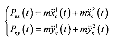
Where m is the mass of the disc corresponding to the roller support.
The force analysis of the disc and the differential equation of the disc motion obtained from the force analysis are similar to those before, only FX and FY need to be replaced by PEX (T) and pey (T) in the formula, and the deformation equation and transfer relationship of the shaft segment are the same as those before.
The calculation method is aimed at the case that the external excitation is simple harmonic excitation, but in general, the excitation PEX (T) and pey (T) to the mold caused by the geometric error between the supporting roller and the centrifugal casting mold surface are periodic non harmonic excitation. In this case, the superposition of simple harmonic excitation needs to be obtained by Fourier expansion, and the displacement caused by each simple harmonic excitation is calculated by transfer matrix method According to the superposition principle, the total vibration response can be obtained by superposition of the response caused by each harmonic excitation.