
In the process of thermal cycle, cracks caused by periodic stress due to internal temperature difference, hindered shrinkage and thermal expansion are called thermal fatigue. Because the thermal fatigue failure will bring very serious consequences, we hope to select the appropriate amount of modifier by comparing and analyzing the influence of the amount of modifier on the thermal fatigue performance of high-strength gray cast iron, so as to optimize the thermal fatigue performance of gray cast iron.
The test gray cast iron samples a, B and C were subjected to thermal fatigue cycle treatment for 500 times. After polishing, the light microscope inspection is as shown in Figure 1. It can be seen that the cracks of samples a, B and C are long, the cracks initiate at the graphite tip, and the flake graphite tip is easy to form stress concentration and accelerate crack growth. The rounder the graphite tip, the smaller the splitting effect, and the greater the hindrance to crack growth, When graphite perpendicular to the crack is encountered, the crack changes direction and continues to expand. Among them, the crack of sample a is wide, and there are many branches of sample B. during the experiment, many new cracks initiate and gradually expand, and the trend of new crack initiation of sample C is the smallest.
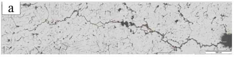
According to the crack length of gray cast iron a, B and C after 500 thermal fatigue cycles, it can be seen that the crack of sample a without modifier is the longest, followed by 75 ferrosilicon inoculation + 1.0wt% For jf-1 composite modified sample B, the crack length of sample C is the shortest, but the crack length of sample B and sample C is similar, but they are much smaller than that of sample a without modifier. It can be analyzed that the thermal fatigue performance of the sample with modifier is better than that without modifier, and the amount of modifier is from 0.8wt% Increase to 1.0wt.% The crack length decreases.
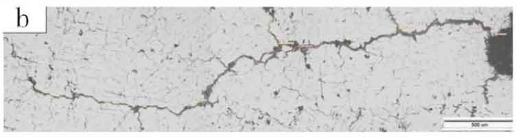
As shown in Fig. 2, the inspection diagram after polishing and corrosion of cracks after 500 thermal fatigue cycles shows that the cracks of samples B and C are narrow and have good thermal fatigue resistance, while the cracks of sample a expand rapidly and are wide. The matrix structure has strong resistance to crack. Under repeated alternating stress, the pearlite matrix will also produce plastic deformation. When the crack occurs at the graphite tip, it will expand slowly on the pearlite matrix. It can be seen from the analysis that the flake spacing of pearlite matrix structure of sample C is small, and pearlite clusters are evenly and densely distributed. Therefore, it has a great obstacle to crack propagation and makes the crack propagation slow. Therefore, it is inoculated with 75sife and the amount of modifier is 0.8wt% C sample has the best thermal fatigue resistance.
In order to study the effect of the amount of modifier on the thermal fatigue properties, we also made a comparative experiment of two groups of samples. The first group of experimental gray cast iron samples a and B were inoculated with 75 ferrosilicon and added with 0.6wt.% and 0.8wt.% Jf-1 modifier was used for composite modification. The C and D samples of the second group of experimental gray cast iron were inoculated with silicon, zirconium and manganese, and 0.6wt.% and 0.8wt.% Jf-1 modifier is used for compound modification, and the composition of gray cast iron a, B, C and D.
The above samples are subjected to thermal fatigue cycle treatment for 500 times. After polishing, the optical microscope inspection is shown in Fig. 3. By observing Fig. 3 and comparing samples a and B, it can be seen that the flake graphite structure of sample a is coarse and there are more large pieces of graphite, which is easy to cause stress concentration and make the graphite tip fragile. Under the action of alternating thermal stress, the graphite tip is easy to become a natural crack source, so the crack is easy to initiate and expand at the graphite tip, and the graphite structure of sample B is relatively fine Uniform, little effect on matrix cleavage, and slow thermal fatigue crack formation and propagation; Comparing samples C and D, it can be seen that although the graphite in sample C is small, there are more large pieces of graphite and the graphite structure distribution is uneven. Therefore, after the thermal fatigue crack is formed, it is easy to expand in the direction of more large pieces of graphite. Although some graphite sheets in sample D are slender, there are less large pieces of graphite and the graphite distribution is more uniform, Therefore, after the crack is generated, it will expand along the slender graphite sheet. When encountering the graphite sheet parallel to the stress direction, it will change the direction and look for the nearest way until another graphite sheet expands along the graphite sheet perpendicular to the stress direction. From the comparative analysis of the two groups of samples, it can be seen that when the content of modifier increases, the graphite sheet becomes fine, round and evenly distributed, so the crack propagation is more hindered, and the thermal fatigue resistance of the sample is better.
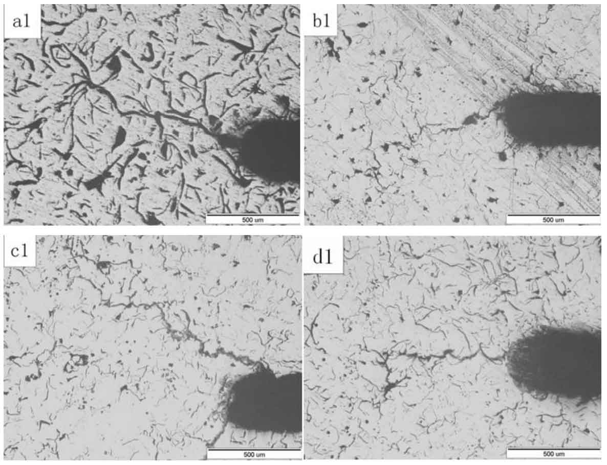
(b1) sampleB—75SiFe+0.8wt.%JF-1 compound modification treatment;
(c1) sample C—Zr-Si-Mn+0.6wt.%JF-1 compound modification treatment;
(d1) sample D—Zr-Si-Mn+0.8wt.%JF-1 compound modification treatment.
The above samples are subjected to thermal fatigue cycle treatment for 1000 times. After polishing, the optical microscope inspection is shown in Fig. 4. Compared with A2 and B2 in Figure 4, it can be seen that the crack of sample a is wide. In the thermal fatigue treatment experiment, with the progress of thermal cycle, many cracks in sample a continue to sprout and expand. Due to the fine and uniform graphite structure, the thermal fatigue crack of sample B is fine and short, and the propagation after the formation of secondary crack is also short; Compared with C2 and D2 in Fig. 4, it can be seen that the main crack of sample C is longer and more secondary cracks are formed, the secondary crack expands longer after formation, and the crack of sample D is shorter. In addition, secondary cracks generally sprout at the coarse block graphite, and the secondary crack propagates shorter after initiation.
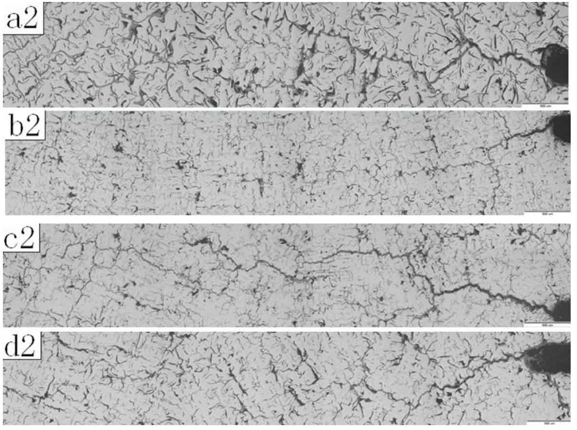
(b2)sample B—75SiFe+0.8wt.%JF-1 compound modification treatment;
(c2) sample C—Zr-Si-Mn+0.6wt.%JF-1 compound modification treatment;
(d2) sample D—Zr-Si-Mn+0.8wt.%JF-1 compound modification treatment.
Table 4.6 shows the crack length of test gray cast iron samples a, B, C and d after 500 and 1000 heat cycles. Compared with the crack length of samples a and B, it can be seen that the crack length of sample B after 500 and 1000 heat cycles is relatively short, but there is little difference between the two crack lengths after 500 heat cycles, but with the increase of heat cycles, The crack length gap is becoming larger and larger. Comparing the crack lengths of C and D samples, it can be seen that after 500 and 1000 thermal cycles, the thermal fatigue crack lengths of both samples are much different, and the crack length of D sample is short. It can be seen that both samples a and B inoculated with 75 ferrosilicon and samples C and D inoculated with silicon, zirconium and manganese are samples with more modifier and shorter crack length. Therefore, we can conclude that the amount of modifier is from 0.6wt% Increase to 0.8wt.% The thermal fatigue resistance becomes better.
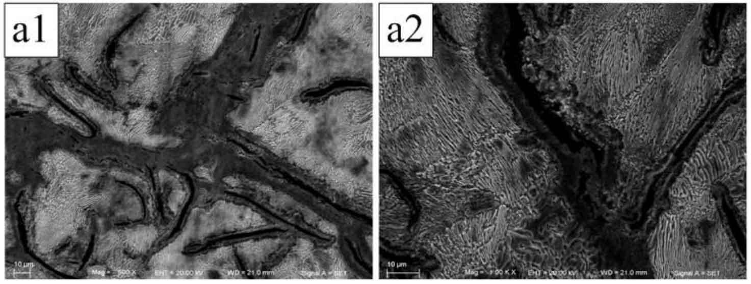
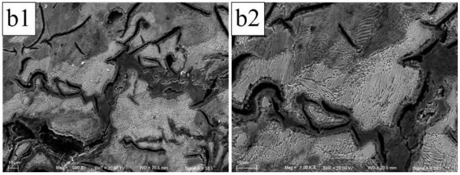
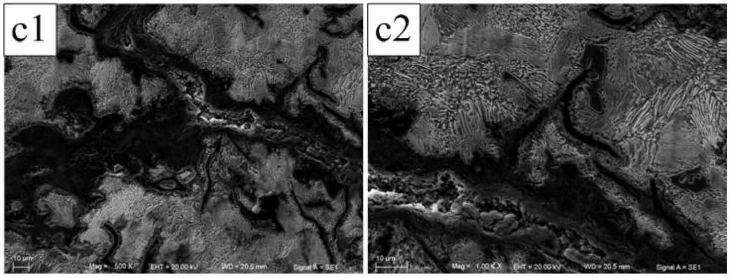
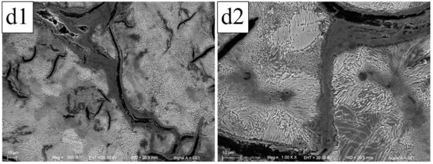
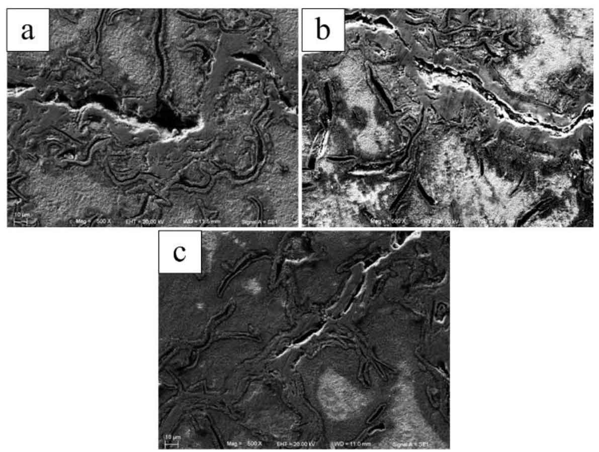
As shown in Figure 5, the crack growth morphology of the experimental gray cast iron after 500 thermal cycles. When the crack grows, it will be hindered by the surrounding pearlite, and the growth speed will slow down or stop. When the stress accumulates to a certain extent, the crack can pass through the pearlite and continue to expand. Comparison sample a B thermal fatigue crack growth morphology (Fig. 5 A1, B1, A2, B2), it can be seen that the crack of sample a is wide and the crack of sample B is narrow; compare the thermal fatigue crack growth morphology of samples C and D (Fig. 5, C1, D1, C2, D2) it can be seen that the crack propagation of sample C is wide and that of sample D is narrow, that is, the increase of the amount of modifier will narrow the thermal fatigue crack. It can also be found from Fig. 5 that secondary cracks are easy to occur along the tip of graphite sheet when flake graphite is encountered in the process of thermal fatigue crack propagation.