
In the realm of advanced manufacturing for aerospace and high-performance applications, the demand for lightweight, high-strength components has never been greater. As a casting engineer specializing in aluminum alloys, I have dedicated significant effort to refining sand casting processes to produce critical sand casting parts that meet stringent quality standards. Sand casting, while versatile and cost-effective for complex geometries, presents unique challenges when applied to thin-walled, large, and structurally intricate sand casting parts. This article delves deeply into a comprehensive case study involving a curved frame-shaped aluminum alloy sand casting part, detailing the initial hurdles, root cause analyses, and the multifaceted process improvements that ultimately led to a dramatic increase in yield and quality. The principles discussed are universally applicable to enhancing the production of similar sand casting parts across industries.
The component in question is a cockpit structural element, classified as a Class II casting requiring high metallurgical quality, density, and freedom from defects such as gas pores, slag inclusions, shrinkage porosity, and pinholes. This particular sand casting part, made from ZL116 aluminum alloy with a net weight of approximately 20 kg, exemplifies the challenges inherent in producing large, intricate sand casting parts. Its overall envelope dimensions are 928 mm x 597 mm x 328 mm, featuring a curved frame design with highly variable wall thicknesses ranging from 4 mm to 18.5 mm. Most surfaces are irregular curves, making it prone to distortion during heat treatment and susceptible to cracking during straightening due to residual casting and quenching stresses.
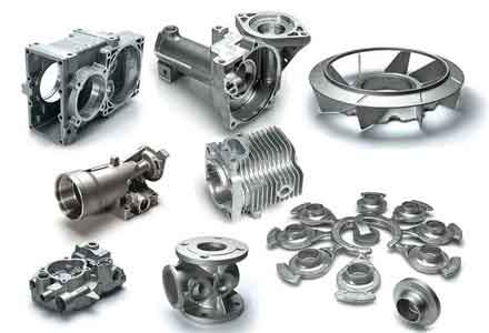
The initial sand casting process employed a conventional two-part green sand mold with a curved parting line following the contour of the sand casting part. The mold cavity was formed by the cope, drag, and a resin sand core. To manage the significant vertical height of the mold assembly, which reached 558 mm including the feeding system, the sprue was positioned at the mid-height of the sand casting part. An open gating system was used with a choke area ratio of $$A_{sprue}:A_{runner}:A_{ingate} = 1.0:3.0:4.4$$. The primary goal was to minimize the drop height and potential turbulence. However, this initial setup proved insufficient for producing sound sand casting parts.
| Defect Type | Primary Location on Casting | Appearance/X-Ray Indication | Initial Occurrence Rate |
|---|---|---|---|
| Gas Porosity & Slag Inclusions | Random distribution throughout the sand casting part | Shiny, round pores; oxidized surfaces; irregular slag patches | High (~60% of scrap) |
| Shrinkage Porosity | Near ingates, process lugs, and specific thick sections (Points A, B, C) | Dispersed micro-porosity in radiographs | Significant (~25% of scrap) |
| Pinhole Porosity | Thick planar sections (Points D, E) | Fine, scattered pinpoints in radiographs | |
| Heat Treatment Distortion | Overall casting geometry, especially arc height dimensions | Unpredictable warping beyond machining allowances | Universal in early batches |
The initial trial production of 37 sand casting parts yielded only 5 acceptable pieces, a mere 13.5% yield. This necessitated a rigorous root cause analysis. For gas and slag defects, while melt treatment and pouring practices were controlled, the gating system design was identified as the critical failure point. The sprue height, even at its mid-position, was 404 mm. The velocity of the metal stream at the sprue exit, governed by Torricelli’s law, is given by:
$$v = \sqrt{2gh}$$
where \(v\) is the exit velocity, \(g\) is gravitational acceleration (9.81 m/s²), and \(h\) is the effective metallostatic head. For our initial setup, \(h \approx 0.404 \, \text{m}\), yielding \(v \approx 2.81 \, \text{m/s}\). This high-velocity stream impinged on the sprue well with enough kinetic energy to erode the mold sand, introducing both sand inclusions and entrapped air into the metal flow. Furthermore, the runner system lacked proper flow stabilization mechanisms, leading to turbulent flow that further promoted gas entrapment within the sand casting parts.
Shrinkage porosity in sand casting parts is fundamentally a thermal management issue. The localized superheating caused by metal flowing through the ingates created last-to-freeze zones. Without adequate feeding, these zones developed dispersed shrinkage. The solidification time \(t_f\) for a section can be approximated by Chvorinov’s rule:
$$t_f = B \left( \frac{V}{A} \right)^n$$
where \(V\) is volume, \(A\) is surface area, \(B\) is a mold constant, and \(n\) is an exponent (typically ~2). In areas like the ingates and thick sections (A, B, C), the higher \(V/A\) ratio led to longer solidification times, creating isolated liquid pools vulnerable to shrinkage. The original design had insufficient feeding capacity to compensate for the solidification shrinkage of aluminum alloys, which is approximately 6-7% by volume.
Pinhole formation, particularly in thick sections D and E, is directly linked to hydrogen solubility in aluminum. The solubility of hydrogen \(C_H\) in molten aluminum decreases exponentially with temperature \(T\):
$$C_H \propto \exp\left(-\frac{\Delta H}{RT}\right)$$
where \(\Delta H\) is the heat of solution and \(R\) is the gas constant. During slow cooling of thick sections, hydrogen rejected from the solidifying metal coalesces into fine bubbles trapped by the advancing solidus front. The critical solidification velocity \(v_{crit}\) to suppress pore formation is related to the diffusion coefficient of hydrogen \(D\) and the temperature gradient \(G\):
$$v_{crit} > \frac{D \cdot G}{C_0 – C_s}$$
where \(C_0\) is initial hydrogen concentration and \(C_s\) is solubility in the solid. The original process, lacking intentional cooling in these areas, resulted in \(v < v_{crit}\), allowing pinholes to form in these sand casting parts.
Heat treatment distortion stemmed from the combination of low high-temperature strength, non-uniform section thickness, and the casting’s large, unrestrained arc shape. When heated to solution treatment temperatures (~500°C for ZL116), the yield strength of the alloy drops significantly. Under its own weight, supported only at certain points during horizontal furnace loading, the thin-walled frame underwent plastic deformation. The distortion \(\delta\) can be conceptually related to stress relaxation under creep conditions:
$$\delta \approx \int \dot{\epsilon}(T, \sigma) \, dt$$
where \(\dot{\epsilon}\) is the creep strain rate, a function of temperature \(T\) and applied stress \(\sigma\) (here, primarily from self-weight). The original process did not account for this mechanically.
Comprehensive Process Improvement Strategy for Sand Casting Parts
The revised sand casting process, depicted schematically below, involved a holistic approach targeting each defect mechanism. The core philosophy was to control fluid flow, enhance directional solidification, accelerate cooling where needed, and provide mechanical support.
| Process Element | Initial Design | Optimized Design | Function & Rationale |
|---|---|---|---|
| Sprue Well | Small, shallow | Larger volume, deeper well with steel wool insert | Dissipates kinetic energy (\( \Delta KE = \frac{1}{2}m(v_i^2 – v_f^2) \)), traps slag, promotes laminar flow into runner. |
| Runner & Ingates | Open system, 3 ingates | Filtered system, 5 ingates with ceramic foam filters at each ingate | Increases feeding paths, reduces superheating per ingate. Filters remove inclusions and promote non-turbulent filling. The new gating ratio was adjusted to better balance flow. |
| Chills | None | Custom-shaped chills at Sections A, B, D, E | Increases local cooling rate (\(G \cdot v\)), modifies solidification sequence. At D/E, accelerates cooling to suppress pinholes (\(v > v_{crit}\)). At A/B, shifts thermal center to aid feeding. |
| Feeders (Risers) | Limited, poorly placed | Two open top risers above B/C, one blind riser between lugs | Provides liquid metal feed to solidifying hot spots. Riser volume designed using the modulus method: \(M_{riser} = k \cdot M_{casting}\) where \(M = V/A\), ensuring risers solidify last. |
| Geometry Modifications | Sharp junctions | Increased fillet radii at stress-concentration points (lugs) | Reduces stress intensity factor \(K_I\) during quenching and straightening, preventing hot tearing. \(K_I \propto \sigma \sqrt{\pi a}\) where \(a\) is flaw size; larger radii reduce \(\sigma\). |
| Heat Treatment Support | Castings laid horizontally | Castings suspended vertically with support pads; temporary stiffening ribs added | Minimizes bending moment \(M\) due to self-weight (\(M = F \cdot d\)). Vertical hanging and ribs increase effective section modulus, reducing stress \(\sigma = M/S\). |
| Straightening Method | Manual, unguided | Using a dedicated correcting die fixture with layout marking | Provides controlled, measurable plastic deformation to achieve final dimensions within tolerance. |
The implementation of these changes required precise engineering. For the gating system, the inclusion of filters and an enlarged sprue well fundamentally altered the fluid dynamics. The pressure drop \(\Delta P\) across a ceramic foam filter can be estimated using the Darcy-Forchheimer equation for flow through porous media:
$$\Delta P = \frac{\mu L}{K} v + \beta \rho L v^2$$
where \(\mu\) is dynamic viscosity, \(L\) is filter thickness, \(K\) is permeability, \(\beta\) is the inertial coefficient, and \(\rho\) is density. This pressure drop helps to dampen turbulence and evenly distribute flow into the multiple ingates, ensuring a more uniform temperature field in the cavity of the sand casting part.
The placement and design of chills are critical. Chills act as heat sinks, extracting heat at a rate governed by the interface heat transfer coefficient \(h_{interface}\) and the temperature difference. The effectiveness of a chill in preventing shrinkage in a sand casting part can be modeled by ensuring that the solidification time of the chilled section \(t_{f,chill}\) is less than that of the adjacent feeding section \(t_{f,feed}\):
$$t_{f,chill} = B \left( \frac{V_{chilled}}{A_{effective}} \right)^2 < t_{f,feed}$$
\(A_{effective}\) is increased by the chill’s conductive area. For pinhole suppression at sections D and E, the goal is to achieve a high temperature gradient \(G\) and solidification rate \(v\). The use of chills directly increases \(G\), thereby raising the product \(G \cdot v\), which must exceed a critical value for soundness.
The feeding system was redesigned using numerical methods in principle. The required riser neck modulus \(M_n\) to ensure it remains open longer than the casting section modulus \(M_c\) is:
$$M_n > M_c \cdot f$$
where \(f\) is a safety factor accounting for alloy feeding characteristics. The risers were placed following thermal analysis to feed the identified hot spots in the sand casting part sequentially.
Validation and Results in Production of Sand Casting Parts
Upon implementing the optimized process, a batch of 65 sand casting parts was produced. The yield increased dramatically to 58 acceptable castings, representing an 89.2% success rate. Radiographic inspection, mechanical testing, and dimensional checks confirmed that the sand casting parts met the stringent Class II standards (equivalent to HB963-2005). The defect distribution was virtually eliminated.
| Performance Indicator | Initial Process (Baseline) | Optimized Process | Improvement Factor |
|---|---|---|---|
| Overall Yield (Acceptable Parts) | 13.5% | 89.2% | ~6.6x |
| Incidence of Gas/Slag Defects | ~60% of scrapped parts | <2% of produced parts | ~30x reduction |
| Incidence of Shrinkage Porosity | ~25% of scrapped parts | Negligible (<1%) | ~25x reduction |
| Incidence of Pinholes (Sections D/E) | Present in >80% of parts | Eliminated | Complete elimination |
| Dimensional Rejection (After Heat Treat) | ~80% of parts required major rework/scrap | <5% minor corrections needed | ~16x reduction in distortion issues |
| Average Straightening Time per Part | High, unpredictable | Reduced and standardized | Significant time savings |
The success of this project underscores several fundamental principles for producing high-integrity sand casting parts. First, for tall sand casting parts, meticulous attention must be paid to the hydraulic design of the gating system. Simply reducing sprue height is not enough; positive steps like sprue well enlargement, flow-damping materials, and filtration are essential to achieve laminar, non-erosive filling and prevent random defects in sand casting parts.
Second, the strategic use of chills is a powerful tool for managing solidification in sand casting parts. They are not merely for accelerating cooling but for actively controlling the temperature gradient and solidification sequence. When combined with properly sized and placed feeders, they can effectively eliminate both shrinkage porosity and gas-related pinholes in critical sections of sand casting parts. The thermal interactions can be complex, often requiring iterative simulation or empirical tuning, but the results justify the effort.
Third, the challenge of heat treatment distortion for large, thin-walled, frame-shaped sand casting parts cannot be overlooked in the process design phase. Proactive measures, such as adding temporary support ribs and optimizing the furnace loading configuration, are far more effective than attempting to correct major distortions afterward. The use of a dedicated correcting fixture, coupled with layout marking, brings precision and repeatability to the straightening operation, ensuring the final dimensions of the sand casting part are consistently achieved.
In conclusion, the journey from a 13.5% to an 89% yield for this complex aluminum alloy sand casting part demonstrates that systematic, science-based process optimization is paramount. By addressing the root causes of defects through improved fluid dynamics, controlled solidification via chills and risers, and proactive distortion management, we can reliably produce high-quality, complex sand casting parts. The methodologies detailed here—from fundamental formulas to practical table-based comparisons—provide a robust framework for engineers tackling similar challenges in the sand casting of critical components. The continuous pursuit of such optimizations ensures that sand casting remains a competitive and capable process for manufacturing the demanding sand casting parts required by modern technology.