
The transition from traditional foundry methods to advanced, automated processes represents a pivotal shift in modern manufacturing. Having been directly involved in the planning and execution of a major foundry transformation, I can attest to the profound impact of adopting lost foam casting technology. This narrative details our journey of retrofitting an existing silicate ester-bonded sand foundry with a fully automated lost foam casting line, a project driven by the imperative to enhance efficiency, improve working conditions, and achieve superior environmental performance.
The global foundry industry has long sought alternatives to conventional sand casting processes, which are often characterized by high labor intensity, poor working environments, and suboptimal surface finish on castings. Since its inception, lost foam casting has been the subject of extensive research and application worldwide. Its unique advantages—design flexibility, near-net-shape capability, and environmental friendliness—have made it a cornerstone for foundries aiming to upgrade their technological base. Our project was initiated to address the limitations of our previous water glass sand process, which suffered from low sand reclamation rates, dusty operations, and inconsistent casting quality. Through rigorous process experimentation and systematic redesign, we successfully implemented an automated lost foam casting production system, yielding remarkable economic and environmental returns.
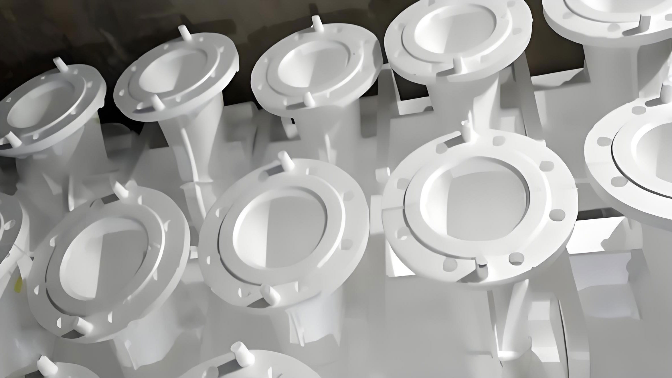
1. Foundational Transformation: The White Pattern and Coating Zone
The heart of lost foam casting lies in the production of the expendable foam pattern, or “white model.” We established two complementary production methods within our revamped facility. For high-volume, standardized components, we employ模具发泡成型 (mold foaming). This involves pre-expanding expandable polystyrene (EPS) or similar bead materials using a batch-type steam pre-expander, followed by automatic molding in vertical成型机 (forming machines). The key parameters here are steam pressure, temperature, and cycle time, which govern bead fusion and final pattern density. For the relationship between final foam density ($\rho_f$) and pre-expansion density ($\rho_p$), we control it through the expansion ratio, often defined as:
$$ E_r = \frac{\rho_p}{\rho_f} $$
where a higher $E_r$ indicates greater expansion and lower final density, impacting gas generation during casting.
For low-volume or highly complex prototypes, we utilize CNC foam cutting machines. This offers exceptional flexibility. The cutting path is governed by a digital model, and the kerf width ($k$), a critical parameter affecting dimensional accuracy, is a function of the hot-wire temperature ($T_w$) and feed rate ($v_f$), which can be empirically modeled as:
$$ k \propto \frac{T_w}{v_f} $$
We repurposed the existing mold storage and infrastructure for pattern assembly, utilizing six bonding stations. Following assembly, patterns require a refractory coating. We installed two flow-coating units for medium-sized patterns, while dip-coating and brushing are available for others. The coating thickness ($\delta_c$) is crucial for metal penetration resistance and must be controlled precisely. It relates to coating viscosity ($\eta$), dipping/flowing time ($t$), and the withdrawal/flow rate ($v$). A simplified relation for dip-coating is given by the Landau-Levich equation:
$$ \delta_c \approx 0.94 \frac{(\eta v)^{2/3}}{\gamma_{lv}^{1/6} (\rho g)^{1/2}} $$
where $\gamma_{lv}$ is the liquid-vapor surface tension, $\rho$ is the coating density, and $g$ is gravity.
The most significant upgrade in this zone was the drying chamber. We replaced conventional heating with an air-source heat pump system. Its Coefficient of Performance (COP), defining its efficiency, is:
$$ COP = \frac{Q_H}{W} $$
where $Q_H$ is the heat delivered to the drying chamber and $W$ is the electrical work input. Our system operates at a COP between 3.0 and 4.0, meaning it delivers 3 to 4 units of heat for every unit of electricity consumed, resulting in energy savings of approximately 20-30% compared to resistance heating. This system provides a stable, controlled drying environment critical for coating integrity.
| Method | Best For | Key Equipment | Flexibility | Typical Lead Time |
|---|---|---|---|---|
| Mold Foaming | High-volume, standard parts | Pre-expander, Automatic Molding Machines | Low | Weeks (includes mold fabrication) |
| CNC Cutting | Prototypes, Low-volume, Complex geometry | CNC Foam Cutting Machine | Very High | Days |
2. The Core Automation: Black Area Production Line
The “black area”—comprising molding, pouring, and cooling—underwent the most radical automation. Our starting point was a simple mold loop line. The new automated lost foam casting line was designed around several key engineering decisions.
2.1 Flask Design and Sand Dynamics
Our product focus is medium-to-small steel castings. Based on the maximum casting dimensions and the fundamental rule of a minimum sand wall thickness ($d_{min}$) of 200 mm, the internal flask dimensions were calculated. For a casting of length $L_c$ and height $H_c$, the flask length $L_f$ and height $H_f$ are:
$$ L_f = L_c + 2 \cdot d_{min} $$
$$ H_f = H_c + d_{min} + d_{top} $$
where $d_{top}$ is the covering sand depth. With $L_c^{max} = 1800$ mm and $H_c^{max} = 500$ mm, we designed flasks with internal dimensions of 2300 mm x 2300 mm x 1000 mm. The flask features five-sided vacuum chambers and four conical bottom discharge outlets to enhance sand flow and reduce dust during shakeout.
2.2 Multi-Axis Vibration Compaction
Replacing the simple vertical jolt table was crucial. Dry, unbonded sand must be compacted uniformly around the complex foam cluster. We installed programmable, multi-axis (3D) vibration tables controlled by PLC. The compaction process is governed by parameters like vibration time ($t_v$), frequency ($f$), amplitude ($A$), and direction. The transmitted energy ($E$) to the sand bed can be conceptually related to these parameters:
$$ E \propto \int_{0}^{t_v} A^2(t) \cdot f^3(t) \, dt $$
The PLC allows operators to set distinct compaction recipes for different pattern clusters, ensuring optimal sand fill and rigidity.
2.3 Automated Line Layout and Control
The entire black area operates as an interconnected system. The layout is a testament to integrated material flow. The process sequence is as follows:
- Empty flask is transported to the sand-filling station.
- Base sand is added via a repositionable belt from the sand reclamation system.
- Foam pattern cluster is placed manually.
- Flask moves to the vibration station for programmable compaction.
- A plastic film is placed, and cover sand is added.
- A transfer car moves the flask to a dedicated pouring station.
- The flask auto-connects to the vacuum system (maintained at ~ -0.04 MPa).
- A pouring ladle car delivers molten steel.
- Post-pour, the flask is transferred to a sealed cooling tunnel.
- After a predetermined cooling time, the flask proceeds to shakeout.
- The empty flask returns to the start via a roller conveyor loop.
A central PLC is the nerve center, coordinating all movements (conveyors, transfer cars, pour ladle car), actuator states (valves, vibrators), and process parameters. It offers both automatic cycle and manual control modes, with a human-machine interface (HMI) providing real-time status and alarm monitoring.
| Subsystem | Key Parameter | Design Value / Specification | Control Method |
|---|---|---|---|
| Flask | Internal Dimensions | 2300 x 2300 x 1000 mm | Fixed Design |
| Sand Filling | Filling Rate | Up to 30 t/h | PLC timed control |
| Vibration Table | Modes, Frequency, Time | 3D, 0-100 Hz, 0-120 s | PLC recipe control |
| Vacuum System | Operating Pressure | Approx. -0.04 MPa | Valve regulation, dual pumps |
| Cooling Zone | Capacity, Control | 30 flasks, Temperature-based | PLC with temp. feedback |
3. The Circulatory System: Sand Reclamation and Cooling
In lost foam casting, sand is a reusable resource. Our system is designed to process ceramic proppant (a type of spherical sand) at 20 t/h, with a recovery rate exceeding 96%. The critical challenge is cooling the sand from near-metal temperatures to below 50°C for reuse. We implemented a two-stage cooling system.
Stage 1: Rotary Drum Cooler. Hot sand from shakeout is screened and magnetically cleaned before entering a rotary cooler. Heat removal ($Q_1$) in this concurrent flow system is approximated by:
$$ Q_1 = \dot{m}_s \cdot c_{p,s} \cdot (T_{s,in} – T_{s,out1}) = \dot{m}_{w1} \cdot c_{p,w} \cdot (T_{w,out1} – T_{w,in}) $$
where $\dot{m}_s$ is sand mass flow rate, $c_{p,s}$ is sand specific heat, $T_{s,in/out}$ are sand temperatures, $\dot{m}_{w1}$ is cooling water flow, and $T_{w,in/out}$ are water temperatures.
Stage 2: Vertical Tower Cooler. The sand is then elevated to a vertical forced-convection cooler. This stage provides precise temperature control. The final sand temperature ($T_{s,out2}$) is the critical control variable. The PLC modulates cooling water flow ($\dot{m}_{w2}$) and sand discharge rate based on real-time measurement of $T_{s,out2}$ to maintain:
$$ T_{s,out2} \leq 50^\circ C $$
The entire sand system is controlled by a dedicated PLC, ensuring automated, continuous, and temperature-stable sand supply to the molding station—a non-negotiable requirement for consistent lost foam casting quality.
4. Environmental Stewardship: Comprehensive Emission Abatement
A modern foundry must be a responsible neighbor. The lost foam casting process generates particulate matter (PM) and, during pouring, volatile organic compounds (VOCs) from the vaporizing foam. Our solution is an integrated “Adsorption + Desorption + Regenerative Catalytic Oxidation” (RCO) system.
Contaminated air is first filtered for PM. The VOC-laden stream then passes through activated carbon adsorbers. The adsorption capacity is related to the properties of the carbon and the VOC species. During the adsorption cycle, VOCs are captured. Periodically, the carbon beds are regenerated by hot air desorption. This concentrated VOC stream (typically 10-20 times more concentrated) is then destroyed in the RCO unit. The RCO operates by heating the stream to a catalytic ignition temperature (typically 300-400°C), where VOCs oxidize exothermically to CO₂ and H₂O:
$$ C_xH_yO_z + (x + \frac{y}{4} – \frac{z}{2}) O_2 \xrightarrow[\text{Catalyst}]{~300-400^\circ C} x CO_2 + \frac{y}{2} H_2O + \text{Heat} $$
The “regenerative” aspect refers to heat exchangers that recover over 95% of the combustion heat to preheat incoming air, making the system highly energy-efficient. This system is monitored by a master PLC, ensuring emissions are consistently below regulatory limits (e.g., Non-Methane Hydrocarbons < 80 mg/m³).
5. Operational Outcomes and Technical Validation
The performance of the automated lost foam casting line has validated all investment and engineering decisions.
5.1 Productivity and Economic Metrics
The contrast with the old manual water glass sand line is stark. Data collected over a sustained period shows definitive improvements.
| Metric | Silicate Ester-Bonded Sand Line (Old) | Automated Lost Foam Casting Line (New) | Improvement / Change |
|---|---|---|---|
| Molding Crew per Shift | 10 persons | 5 persons | -50% |
| Molding Rate | 2 flasks/hour | 3 flasks/hour | +50% |
| Estimated Annual Output | ~6,500 tonnes | ~10,000 tonnes | +54% |
| Sand System Power | 181.1 kW | 50 kW | -72% |
| Pattern Drying Energy Cost/Tonne Casting | Base Reference (100%) | ~80% of base cost | -20% |
| Summer Return Sand Temperature | 40-50°C | Stable < 40°C | Significantly cooler and stable |
5.2 Environmental and Working Condition Metrics
The environmental control system has transformed the shop floor. Post-implementation monitoring shows:
- Particulate Matter (PM) concentration: 3.52 mg/m³ (against a limit of 10 mg/m³).
- Non-Methane Hydrocarbon (NMHC) concentration: 17.9 mg/m³ (against a limit of 80 mg/m³).
These figures represent a dramatic improvement in air quality, enhancing worker safety and comfort.
5.3 Product Quality: Solving the Steel Carburization Challenge
A historical concern in lost foam casting of steels is surface carburization from the carbon-rich foam (traditional EPS is ~92% carbon). For our carbon steel castings (ZG270-500), we adopted a newly developed expandable acrylic-based copolymer foam material with a carbon content of only ~63%. The reduction in potential carbon pickup is significant. Metallurgical analysis confirms the effectiveness. The carbon increase in the subsurface layer (up to 5 mm) is less than 0.05%. Chemical analysis of castings from the same heat shows consistency between ladle sample and cast product, meeting all specification requirements.
| Element | Specification Limit (max or range) | Ladle Analysis | Cast Sample #1 | Cast Sample #2 | Cast Sample #3 |
|---|---|---|---|---|---|
| C | ≤ 0.40 | 0.29 | 0.30 | 0.31 | 0.29 |
| Si | ≤ 0.60 | 0.37 | 0.38 | 0.37 | 0.37 |
| Mn | ≤ 0.90 | 0.82 | 0.81 | 0.81 | 0.80 |
| P | ≤ 0.035 | 0.022 | 0.022 | 0.021 | 0.021 |
| S | ≤ 0.035 | 0.018 | 0.019 | 0.017 | 0.018 |
In conclusion, the automation and transformation of our foundry around lost foam casting principles have proven to be a resounding success. The project has delivered on its core objectives: drastically improved productivity through PLC automation and refined material handling; significant energy savings via advanced heat pump drying and efficient sand cooling; a superior and safer working environment enabled by integrated emission control; and high-integrity castings free from traditional process defects. This comprehensive upgrade demonstrates that lost foam casting is not merely an alternative casting method but a viable, efficient, and sustainable platform for the modern, competitive foundry.