1. Large hydraulic press
Composite squeeze casting is a new squeeze casting method proposed in. At present, there is no special forming equipment, but the general four column hydraulic press can be modified to realize the functions required for the composite squeeze casting of large parts. As the formed parts are large, the general hydraulic press must have a large forming pressure according to the specific pressure parameters selected in the previous section. After comprehensive evaluation, 16000kN vertical casting machine (model ly-1600) was selected as the squeeze casting forming hydraulic press. The hydraulic press adopts a combined frame structure. Its upper beam, movable beam, base and column are processed and manufactured respectively, and then assembled by fastening. The upper crossbeam and the base are pre tensioned and connected by prestressed tie rods and supporting parts to form a rigid frame, which has good rigidity. The hydraulic press has a main piston cylinder and two piston cylinders for auxiliary extrusion and return.
2. Mold filling system
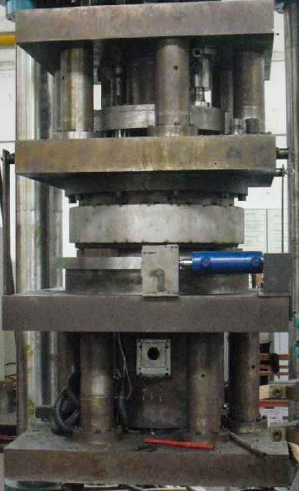
The filling system of composite squeeze casting is modified by the injection system of indirect squeeze casting, and the passive pressing function of the filling head is added, that is, when the upper mold is applied with pressure, if the pressure on the filling head does not exceed the set value, the filling head must be maintained in the position in the filling cavity. If the pressure exceeds the set value, the filling head automatically retracts until the pressure on it is less than the set value. The mold filling device of the mold filling system adopts the hanging type, which is composed of two suspenders, a mold filling hydraulic cylinder and a mold filling head. The model of the hydraulic press and the mold filling device is shown in Figure 1.
According to the process requirements of composite squeeze casting, the hydraulic press and filling device must be able to achieve the following actions: rapid lowering of the movable beam, pressurization of the movable beam, pressure maintaining of the movable beam, pressure relief of the movable beam, return of the movable beam, rapid rise of the filling head, pressure maintaining of the filling head, pressure relief of the filling head, return of the filling head and passive pressing of the filling head. The upward speed of the filling head must meet the requirements of the filling speed of large parts. At the same time, while the hydraulic press drives the upper die and the moving coil to press down, the filling head must also have the function of passive pressing.
| Design parameters | Numerical value | Unit |
| Liquid pressure | 25 | MPa |
| Working stroke | 1950 | mm |
| Opening height | 3050 | mm |
| Worktop | 2540×2200 | mm |
| Master cylinder pressure | 14000 | KN |
| Return cylinder pressure | 1000 | KN |
| Cavity pressure | 6300 | KN |
| Idle speed | 180 | mm/s |
| Return speed | 100 | mm/s |
| Injection velocity | 44 | mm/s |
| Fuselage structure | Three beam four column type | — |
| Overall dimensions (height × long × Width) (mm) | 11500X3540X3200 | mm |
The hydraulic system of the universal casting machine needs to be reformed because of many actions required. The maximum pressure of the hydraulic system oil circuit of the reformed testing machine is 25MPa, including one main hydraulic cylinder, two return cylinders, one filling cylinder, 30 directional valves of different types, 12 pressure control valves, several hydraulic control valves and one-way valves. The hydraulic power is provided by 8 hydraulic pumps and electric machines. The same hydraulic cylinder is used for die closing and extrusion, and the speed and pressure curve of the hydraulic cylinder are adjusted through the hydraulic valve to achieve the functions of rapid lowering of the movable beam and slow high-pressure extrusion. The main parameters of the hydraulic press and the mold filling device after the transformation are shown in the table.
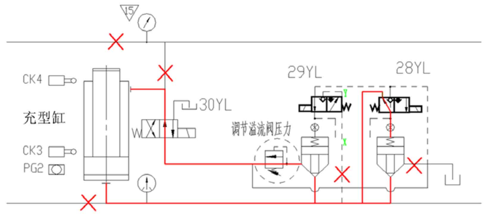
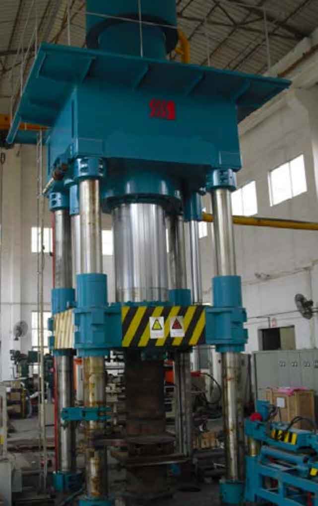
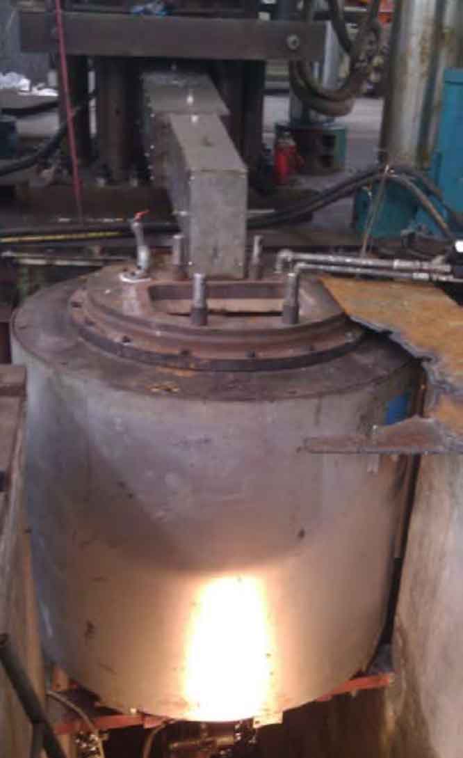
When the movable beam is pressurized and maintained, the principle of passive pressing of the filling head is shown in Figure 2. When the pressure transmitted by the upper mold through the molten metal on the filling head does not exceed the pressure set by the overflow valve in the oil circuit, the filling head is in a static state; When the pressure received by the filling head exceeds the pressure set by the overflow valve, the filling head will automatically return, and the rod cavity in the filling cylinder will automatically replenish oil. The main body of the modified composite squeeze casting system is shown in Figure 3.
3. Molten liquid conveying system
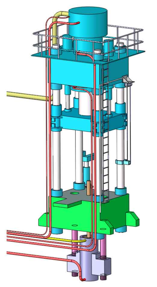
The molten liquid conveying method used in the forming experiment adopts the molten liquid conveying system designed in Chapter 3 and tested and verified, as shown in Figure 4.
4. Mold manufacturing
According to the research results, the floating rigid support mold structure can meet the needs of the composite squeeze casting method. Therefore, the mold of the trial parts adopts this structure. After the relevant structure is refined and improved, the mold manufacturing is completed. The results are shown in Figure 5. The medium cavity of the die is made of heat-resistant die steel H13. In order to ensure the temperature of molten metal during squeeze casting, a special heating sleeve is made for the filling cavity, so that the measured temperature of the filling cavity can reach 500 ℃ during the process implementation.