
In my extensive experience with lost foam casting processes, I have encountered numerous cases of component failures, but the brittle fracture of ZG35CrMnSi steel pin rails used in coal mining scraper conveyors stands out due to its batch-wise occurrence. This article delves into a comprehensive failure analysis, employing macro- and micro-fractography, chemical composition analysis, and mechanical property testing. The findings reveal critical insights into how inherent aspects of the lost foam casting process, such as slag inclusion formation and carbon pick-up, compromise material integrity. Through this first-person investigation, I aim to outline the root causes and propose definitive preventive measures to enhance the reliability of castings produced via lost foam casting.
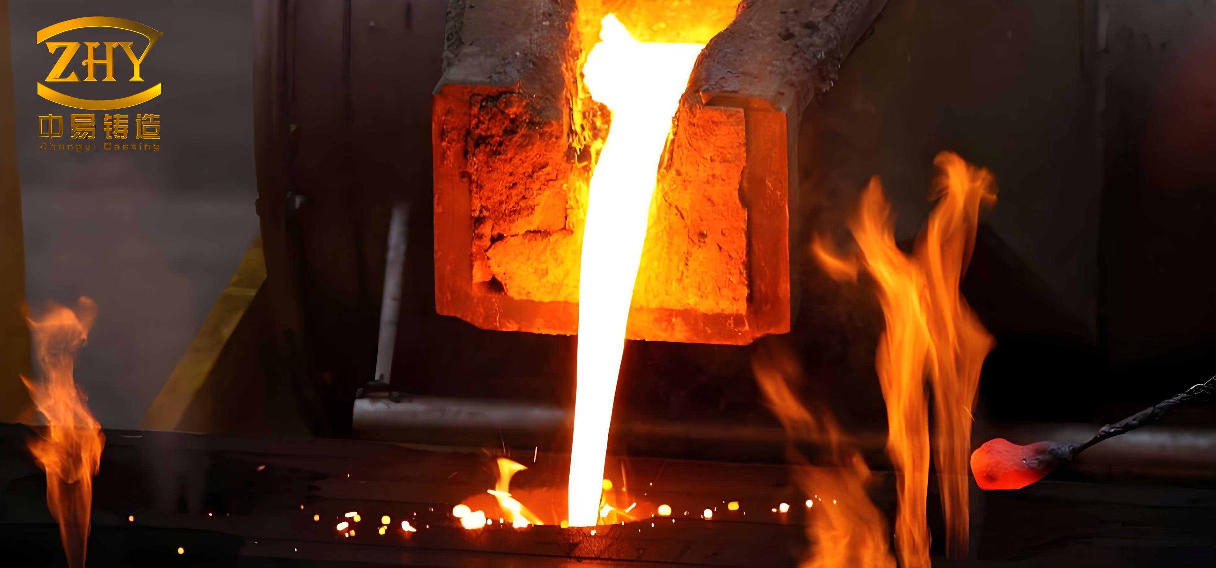
The lost foam casting technique, while advantageous for complex geometries, introduces unique challenges. For the pin rail castings, with dimensions approximately 650 mm × 250 mm × 300 mm, the standard procedure involved using EPS (expanded polystyrene) patterns with a density of 32 kg/m³. The molding and pouring parameters were set within typical ranges for lost foam casting: a pouring temperature of 1590–1620°C and a vacuum pressure of -0.053 to -0.067 MPa. However, post-service fractures indicated a systemic issue tied directly to the lost foam casting method.
Methodological Approach to Failure Investigation
My analysis began with a systematic examination of fractured pin rails and accompanying test specimens cast under identical lost foam casting conditions. The methodology was structured to isolate factors specific to lost foam casting.
| Analysis Type | Sample Description | Standard/Equipment |
|---|---|---|
| Macroscopic Fractography | As-cast tensile test bar from same batch | Visual and stereo microscope |
| Microscopic Examination | Polished and etched specimens from fracture zone | Optical microscope (200x, 1000x) |
| Chemical Composition | Material sampled directly from fracture surface | Optical emission spectrometry |
| Mechanical Testing | Standard tensile test bars (Ø10 mm) | Universal testing machine (GB/T 228-2002) |
A fundamental relationship in fracture mechanics, often considered when assessing brittle failure, is the stress intensity factor. For a material containing flaws like slag inclusions, the critical stress intensity factor \( K_{IC} \) can be expressed as:
$$ K_{IC} = Y \sigma_f \sqrt{\pi a} $$
where \( \sigma_f \) is the fracture stress, \( a \) is the characteristic flaw size (e.g., slag inclusion diameter), and \( Y \) is a geometric factor. In lost foam casting, the presence of numerous inclusions significantly reduces the effective \( K_{IC} \), promoting brittle fracture.
Results and Detailed Analysis
Macroscopic and Microscopic Fracture Characteristics
The macroscopic fracture surface exhibited a distinct honeycomb-like, coarse structure with visible slag inclusions, unequivocally indicating a brittle fracture mode with no significant plastic deformation. This morphology is a direct consequence of the lost foam casting process, where pattern decomposition products can become entrapped.
Microscopic examination of unetched samples revealed a high density of non-metallic inclusions, some associated with voids and micro-cracks. The microstructure after etching showed inhomogeneous phases, including lath-like or acicular structures, and a localized directionality. The area fraction of inclusions \( A_i \) was remarkably high, which I quantified from multiple micrographs. The average inclusion density \( \rho_{inc} \) can be related to the toughness degradation:
$$ \Delta K_{IC} \propto – \alpha \cdot \rho_{inc} $$
where \( \alpha \) is a material constant. For lost foam casting, \( \rho_{inc} \) tends to be higher due to residual pattern pyrolysis products.
Chemical Composition Deviation
Chemical analysis of the fractured material showed significant deviations from the standard ZG35CrMnSi specification, particularly for elements influencing hardenability and toughness. The results are summarized below.
| Element | Measured Composition (wt%) | Standard Specification (wt%) | Deviation Impact |
|---|---|---|---|
| C | 0.42 | 0.32–0.39 | Substantial increase promotes brittleness |
| Si | 1.43 | 1.10–1.40 | Upper limit exceeded; may reduce toughness |
| Mn | 1.34 | 0.80–1.10 | Significant overshoot; lowers toughness |
| Cr | 0.96 | 1.10–1.40 | Below limit; reduces hardenability |
| P | 0.037 | ≤0.040 | Acceptable |
| S | 0.034 | ≤0.040 | Acceptable |
The carbon content is critically high. In lost foam casting, carbon pick-up \( \Delta C \) is a known phenomenon due to the decomposition of the hydrocarbon-based pattern. It can be modeled as:
$$ C_{cast} = C_{melt} + \Delta C_{EPS} $$
where \( \Delta C_{EPS} \) is the incremental carbon from the EPS pattern. For this lost foam casting process, \( \Delta C_{EPS} \) was estimated to be approximately 0.03–0.05 wt%, contributing to the超标. The combined effect of high C, Si, and Mn drastically reduces the ductile-to-brittle transition temperature, as approximated by:
$$ T_{DBT} \approx \beta_0 + \beta_1 (\%C) + \beta_2 (\%Si) + \beta_3 (\%Mn) $$
where \( \beta \) coefficients are positive, indicating elevated \( T_{DBT} \) and increased brittle fracture risk at service temperatures.
Mechanical Performance Degradation
Tensile testing revealed a near-total lack of yield plateau and necking, with fracture occurring at an elongation of only 9.4%. The force-displacement curve was almost linear until abrupt fracture. The tensile strength was 900 MPa, but the true indicator of failure is the poor toughness. The reduction in area \( RA \) and elongation \( \epsilon_f \) were severely limited by the inclusions. A modified rule of mixtures can illustrate the effect of slag inclusions on tensile properties:
$$ \sigma_u^{composite} = \sigma_u^{matrix} (1 – V_f^{slag}) + \sigma_u^{slag} V_f^{slag} $$
where \( V_f^{slag} \) is the volume fraction of slag, and \( \sigma_u^{slag} \approx 0 \), thus \( \sigma_u^{composite} \) decreases. More critically, the strain to failure follows:
$$ \epsilon_f^{composite} \approx \epsilon_f^{matrix} \exp(-\gamma V_f^{slag}) $$
where \( \gamma \) is a constant. For the lost foam casting samples, \( V_f^{slag} \) was high, causing exponential drop in ductility.
| Mechanical Property | Measured Value | Typical Expected Range for ZG35CrMnSi |
|---|---|---|
| Tensile Strength | 900 MPa | 850–1000 MPa |
| Yield Strength (0.2% offset) | Not distinctly observed | ≥650 MPa |
| Elongation | 9.4% | ≥12% |
| Hardness (HRB) | 235 | 220–250 |
| Estimated Impact Toughness | Low (from brittle fracture) | ≥30 J at room temperature |
Mechanistic Discussion on Failure in Lost Foam Casting
The synergistic effect of compositional aberrations and extensive slag inclusion formation is the core failure mechanism. In lost foam casting, the pyrolysis of the EPS pattern generates gaseous and liquid residues. If not fully evacuated, these residues transform into slag inclusions within the solidifying metal. The total inclusion volume \( V_{slag} \) can be related to pattern density \( \rho_{pattern} \) and process parameters:
$$ V_{slag} = k \cdot \rho_{pattern} \cdot \left(1 – e^{-t/\tau}\right) $$
where \( k \) is a process constant, \( t \) is the effective pyrolysis time, and \( \tau \) is a time constant. Higher pattern density (like 32 kg/m³ EPS) increases \( V_{slag} \).
Furthermore, carbon pick-up is an intrinsic issue in lost foam casting of steel. The carbon diffusion from the decomposing pattern into the molten metal can be described by Fick’s law adapted for this transient process:
$$ \frac{\partial C}{\partial t} = D \nabla^2 C + S(x,t) $$
where \( D \) is the diffusion coefficient and \( S(x,t) \) is a source term representing carbon release from the pattern. Non-uniform carbon distribution leads to localized hard and brittle zones.
The combined detrimental effect on fracture toughness \( J_{IC} \) can be modeled as:
$$ J_{IC} = J_0 – m_C (\%C – C_0) – m_{slag} \sqrt{A_{slag}} $$
where \( J_0 \) is the base toughness, \( m_C \) and \( m_{slag} \) are coefficients, and \( A_{slag} \) is the average inclusion area. For lost foam casting components, both terms on the right are significant, driving \( J_{IC} \) below the critical threshold for ductile tearing.
Comprehensive Preventive Strategies for Lost Foam Casting
Based on this analysis, I propose a multi-faceted approach to prevent such failures in lost foam casting operations. The strategies target the root causes: slag inclusion minimization and compositional control.
1. Pattern Material and Design Optimization
To reduce slag formation, shift from standard EPS to lower-density co-polymer patterns. The relationship between pattern material and residual slag can be guided by:
$$ Q_{residue} = \int \left( \frac{dm_{pattern}}{dt} \right) \cdot \eta_{conv} \, dt $$
where \( Q_{residue} \) is the mass of unconverted residue, \( dm_{pattern}/dt \) is the pattern decomposition rate, and \( \eta_{conv} \) is the conversion efficiency to gas. For EPS-PMMA or pure PMMA, \( \eta_{conv} \) is higher, reducing \( Q_{residue} \). Furthermore, adopting hollow pattern structures decreases the total polymer mass per casting, directly lowering potential carbon pick-up and slag volume. The modified carbon pick-up equation becomes:
$$ \Delta C_{new} = \Delta C_{EPS} \cdot \left( \frac{M_{pattern, new}}{M_{pattern, original}} \right) $$
where \( M_{pattern} \) is the pattern mass. Hollow designs can reduce \( M_{pattern} \) by 30–50%.
2. Process Parameter Refinement
Adjusting lost foam casting parameters is crucial. A pre-pyrolysis step before pouring can be considered. The vacuum level \( P_v \) and pouring temperature \( T_p \) need optimization to ensure complete pattern removal. An empirical relationship for slag-free yield \( Y_{sf} \) might be:
$$ Y_{sf} = A \cdot \left( \frac{P_v}{T_p} \right)^n \cdot \exp\left(-\frac{E_a}{RT_p}\right) $$
where \( A \) and \( n \) are constants, \( E_a \) is an activation energy for pattern removal, and \( R \) is the gas constant. Higher \( P_v \) and optimal \( T_p \) maximize \( Y_{sf} \).
3. Chemical Composition Control
For lost foam casting of ZG35CrMnSi, the melt chemistry must be adjusted to account for inevitable carbon pick-up. The target ladle composition \( C_{target} \) should be set below the standard lower limit:
$$ C_{target} = C_{lower, spec} – \mu \cdot \Delta C_{expected} $$
where \( \mu \) is a safety factor (e.g., 1.2). Similarly, for Mn and Si, aim for mid-range values to compensate for possible segregation. Implementing rigorous ladle and in-mold inoculation practices can also improve microstructure homogeneity.
4. Alternative Manufacturing Route
For components requiring high toughness, consider reverting to conventional green sand casting for critical sections. The cost-benefit analysis can be framed by comparing the risk of failure \( R \) in lost foam casting vs. sand casting:
$$ R_{LFC} = P_{f, LFC} \cdot C_{f} $$
$$ R_{SC} = P_{f, SC} \cdot C_{f} + \Delta C_{manuf} $$
where \( P_f \) is probability of failure, \( C_f \) is failure cost, and \( \Delta C_{manuf} \) is the manufacturing cost difference. If \( R_{LFC} > R_{SC} \), sand casting is preferable.
5. Enhanced Quality Monitoring
Implement non-destructive testing (NDT) like ultrasonic inspection to detect slag clusters. The detectability is a function of inclusion size and density. A quality index \( QI \) for lost foam casting batches can be defined:
$$ QI = \frac{1}{N} \sum_{i=1}^{N} \left( \frac{K_{IC, measured,i}}{K_{IC, spec}} \right) \cdot \exp(- \lambda \cdot V_{slag,i}) $$
where \( \lambda \) is a weighting factor. Batches with \( QI < 1 \) require corrective actions in the lost foam casting process.
Conclusion
Through this detailed investigation, I have established that the batch brittle fracture of ZG35CrMnSi pin rails is primarily attributable to two interconnected factors inherent to the lost foam casting process: excessive slag inclusions from pattern decomposition and significant carbon pick-up leading to off-specification chemistry. These factors collectively degrade plasticity and toughness, as evidenced by macro/micro observations and mechanical tests. The preventive framework I propose—encompassing pattern material selection (EPS-PMMA/PMMA), hollow design, meticulous chemical control, and process optimization—provides a robust pathway to mitigate these failures. For applications where toughness is paramount, evaluating a shift to sand casting is a prudent consideration. Continuous refinement of lost foam casting parameters, coupled with stringent quality checks, is essential to harness the benefits of lost foam casting while ensuring component integrity. This analysis underscores the critical need for process-tailored material engineering in advanced casting techniques like lost foam casting.