
In my extensive experience with mechanical component failures, the fracture of driving shafts in industrial equipment often leads to significant downtime and safety concerns. Recently, I encountered a case involving a spheroidal graphite cast iron driving shaft from a screw refrigeration compressor that fractured during operation, causing a complete shutdown. The shaft, made of spheroidal graphite cast iron grade QT700-2, had a diameter of 150 mm and a length of 2000 mm. Its manufacturing process included preparation, melting, spheroidizing and inoculation, casting, demolding, grinding, normalizing with air cooling, high-temperature tempering with air cooling, and finally machining. To prevent future incidents and ensure operational safety, I conducted a comprehensive failure analysis using multiple techniques. This article details my investigation, focusing on the root causes of the fatigue fracture, with an emphasis on the material characteristics of spheroidal graphite cast iron. I will present findings through macroscopic and microscopic examinations, chemical and mechanical property analyses, and discuss implications for production improvements.
Driving shafts are critical components in machinery, responsible for transmitting motion, torque, or bending moments. Fracture failure, particularly fatigue-related, is a severe mode of failure that can stem from various factors such as improper processing, microstructural defects, or operational errors. For spheroidal graphite cast iron components, common failure causes include stress concentrations from machining marks, surface damage, non-metallic inclusions, core porosity, and graphite distortion due to insufficient carbon content. In this analysis, I aimed to identify the specific issues leading to the fracture of the spheroidal graphite cast iron driving shaft. By applying systematic methodologies, I sought to provide actionable insights for enhancing the manufacturing and treatment processes of spheroidal graphite cast iron parts.
Experimental Methodology
To analyze the fractured spheroidal graphite cast iron driving shaft, I employed a multi-faceted approach. First, I sectioned samples from the broken shaft using wire cutting for various tests. The analysis included:
- Macroscopic Morphology Examination: I visually inspected the fracture surface to identify patterns indicative of failure modes, such as fatigue marks or brittle features.
- Chemical Composition Analysis: Using a SPECTROMAXx-BT direct reading spectrometer, I determined the elemental composition of both the outer surface and core regions of the spheroidal graphite cast iron shaft. This helped verify if the material met standard specifications for spheroidal graphite cast iron.
- Metallographic Microstructure Observation: I prepared polished samples and etched them with a 4% nitric alcohol solution for 5 seconds to reveal the microstructure. Examination under an optical microscope allowed me to assess graphite morphology, matrix structure, and the presence of secondary phases like cementite.
- Mechanical Property Testing: I conducted tensile tests on longitudinal samples taken from a quarter of the diameter from the outer surface. The stress-strain curves were plotted, and key properties such as tensile strength, yield strength, and elongation were measured and compared to standard values for spheroidal graphite cast iron QT700-2.
- Scanning Electron Microscopy (SEM) Micro-Morphology Analysis: A VEGAⅡ-XMH SEM was used to examine the fracture surface at higher magnifications. This provided details on fatigue striations, fracture paths, and microstructural features. Energy-dispersive X-ray spectroscopy (EDS) was also performed for localized chemical analysis.
- Microhardness Measurement: I used a Vickers microhardness tester with a load of 2 N to determine the hardness of the outer surface and core regions, correlating it with microstructural observations.
These methods enabled a holistic understanding of the failure mechanisms in the spheroidal graphite cast iron driving shaft.
Results and Discussion
My analysis revealed several critical factors contributing to the fracture. Below, I present the findings in detail, incorporating tables and formulas to summarize data and illustrate concepts related to spheroidal graphite cast iron behavior.
Macroscopic Morphology Observations
Upon examining the fracture surface, I observed significant wear due to post-fracture rubbing, but remnants of the original fracture were discernible. The surface appeared rough with no macroscopic plastic deformation, suggesting brittle characteristics typical of certain spheroidal graphite cast iron conditions. Chevron patterns indicated that the crack initiated at the outer surface of the shaft, and beach marks were visible, confirming a fatigue failure mechanism. Additionally, torsional signatures were present, pointing to torsional fatigue as the primary failure mode. This aligns with common fatigue failures in rotating spheroidal graphite cast iron components under cyclic loading.
Chemical Composition Analysis
The chemical composition of the spheroidal graphite cast iron driving shaft was analyzed at both the outer surface and core. Results are summarized in Table 1. All elements, including carbon, silicon, manganese, phosphorus, and sulfur, were within the typical range for spheroidal graphite cast iron, as per standard specifications. This indicates that the base material chemistry was not the direct cause of failure, but microstructural variations could still arise from processing conditions.
| Sample Location | C | Si | Mn | P | S |
|---|---|---|---|---|---|
| Outer Surface | 3.850 | 2.540 | 0.650 | 0.021 | 0.001 |
| Core | 3.840 | 2.630 | 0.690 | 0.018 | 0.001 |
| Typical Spheroidal Graphite Cast Iron Range | 3.600-3.900 | 2.000-2.800 | 0.600-0.800 | <0.100 | <0.070 |
The consistency in composition suggests that the spheroidal graphite cast iron was properly alloyed, but other factors like cooling rates during casting could influence microstructure.
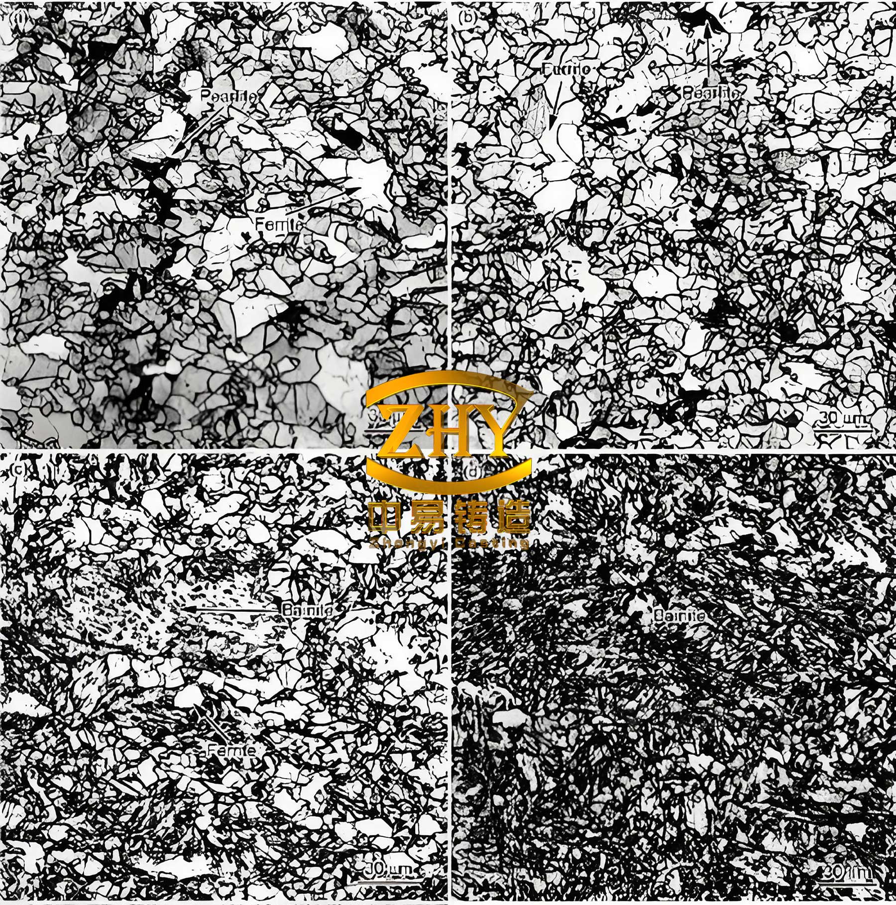
Metallographic Microstructure Analysis
The microstructure of the spheroidal graphite cast iron shaft near the crack initiation zone was examined. In unetched conditions, graphite morphology showed a mix of spheroidal graphite and some vermicular graphite, with notably fewer graphite particles on the outer surface. This is attributed to rapid cooling during casting, which inhibits graphite formation and leads to poor inoculation in spheroidal graphite cast iron. After etching, the matrix structure consisted of pearlite, networked secondary cementite (appearing as white networks), and graphite nodules. The outer surface exhibited a pronounced network of cementite, which embrittles the material. This microstructural anomaly in spheroidal graphite cast iron reduces toughness and promotes crack initiation under fatigue loading.
The presence of networked cementite can be described by the phase transformation in spheroidal graphite cast iron during cooling. For instance, the formation of cementite (Fe$_3$C) from austenite can be expressed as: $$\gamma \rightarrow \alpha + \text{Fe}_3\text{C}$$ where $\gamma$ is austenite and $\alpha$ is ferrite. In this case, excessive cementite at the surface indicates non-equilibrium cooling, detrimental to the ductility of spheroidal graphite cast iron.
Microhardness and Mechanical Properties
Microhardness measurements revealed a disparity between the outer surface and core of the spheroidal graphite cast iron shaft, as shown in Table 2. The higher hardness at the surface (approximately 423 HV$_{2N}$) compared to the core (397 HV$_{2N}$) correlates with the reduced graphite and cemented network, increasing brittleness. This hardness gradient in spheroidal graphite cast iron can be quantified using a simple model: $$H_v = H_0 + k \cdot C_{eff}$$ where $H_v$ is Vickers hardness, $H_0$ is base hardness, $k$ is a constant, and $C_{eff}$ is effective carbon content from cementite. The elevated surface hardness facilitated fatigue crack nucleation.
| Location | Hardness Measurements | Average Hardness |
|---|---|---|
| Outer Surface | 432, 423, 419, 421, 420, 423 | 423 |
| Core | 389, 390, 399, 410, 397, 397 | 397 |
Tensile test results, summarized in Table 3, indicated that the mechanical properties of the spheroidal graphite cast iron shaft were below the standard for QT700-2. The average tensile strength was 525 MPa, yield strength was 379 MPa, and elongation was 4.7%, whereas standard QT700-2 spheroidal graphite cast iron requires 700 MPa tensile strength, 420 MPa yield strength, and 2% elongation. The shortfall in strength, especially in spheroidal graphite cast iron, is often linked to microstructural defects like cementite networks. The stress-strain curve, represented by a typical relationship: $$\sigma = E \epsilon \quad \text{for elastic region}$$ where $\sigma$ is stress, $E$ is Young’s modulus, and $\epsilon$ is strain, showed limited plastic deformation, consistent with brittle behavior.
| Sample | Tensile Strength (MPa) | Yield Strength (MPa) | Elongation (%) |
|---|---|---|---|
| 1 | 512 | 381 | 4.1 |
| 2 | 510 | 377 | 4.2 |
| 3 | 554 | 380 | 5.9 |
| Average | 525 | 379 | 4.7 |
| QT700-2 Standard | 700 | 420 | 2.0 |
The reduced performance underscores how microstructural imperfections in spheroidal graphite cast iron can compromise integrity.
SEM Micro-Morphology and EDS Analysis
SEM examination of the fracture surface revealed fatigue striations in localized areas, confirming fatigue as the failure mechanism in this spheroidal graphite cast iron component. Intergranular fracture features were also observed, aligning with the networked cementite that provided easy crack paths. EDS analysis on the matrix showed primarily iron (95.31%) and silicon (4.69%), with no significant sulfur or phosphorus, indicating that impurity segregation was not a factor. The fatigue crack growth in spheroidal graphite cast iron can be described by Paris’ law: $$\frac{da}{dN} = C (\Delta K)^m$$ where $da/dN$ is crack growth rate per cycle, $\Delta K$ is stress intensity factor range, and $C$ and $m$ are material constants. For spheroidal graphite cast iron with embrittled surfaces, $C$ and $m$ may be higher, accelerating failure.
Discussion on Failure Mechanism
Based on my findings, the fracture of the spheroidal graphite cast iron driving shaft was primarily due to torsional fatigue initiated at the outer surface. The root cause lies in the microstructural deficiencies: sparse graphite distribution and a networked secondary cementite phase. In spheroidal graphite cast iron, graphite nodules act as stress relievers by blunting cracks, but their scarcity at the surface increased stress concentrations. Additionally, cementite networks embrittle the matrix, reducing fatigue resistance. The hardness gradient further exacerbated this, making the surface prone to crack nucleation under cyclic torsional loads. This aligns with fatigue theory where surface conditions dominate life prediction for spheroidal graphite cast iron components. The fatigue life $N_f$ can be estimated using: $$N_f = \frac{1}{C} \int_{a_i}^{a_f} \frac{da}{(\Delta K)^m}$$ where $a_i$ is initial flaw size and $a_f$ is critical size. For this spheroidal graphite cast iron shaft, $a_i$ was effectively enlarged by microstructural defects.
Comparatively, ideal spheroidal graphite cast iron should have uniform graphite dispersion and a pearlitic matrix without continuous cementite. The deviation here likely resulted from rapid cooling during casting and inadequate heat treatment. For instance, the normalizing process may have been too brief, preventing full transformation and leading to retained cementite in spheroidal graphite cast iron. To quantify, the cooling rate $R$ influences cementite formation: $$R > R_c \Rightarrow \text{cementite network}$$ where $R_c$ is a critical rate for spheroidal graphite cast iron. In production, controlling $R$ is key to avoiding such issues.
Conclusions and Recommendations
My failure analysis conclusively identifies that the fracture of the spheroidal graphite cast iron driving shaft was a fatigue failure originating from the outer surface due to poor microstructure. Specifically, the lack of graphite nodules and the presence of a networked secondary cementite phase embrittled the surface, creating favorable conditions for crack initiation and propagation in spheroidal graphite cast iron. The mechanical properties were below standard, and microhardness variations further contributed to the failure.
To prevent recurrence in spheroidal graphite cast iron components, I recommend several improvements in manufacturing and processing:
- Enhanced Casting Process Control: Increase mold temperatures during pouring to reduce cooling rates, ensuring better graphite formation in spheroidal graphite cast iron. Larger machining allowances can help remove surface defects post-casting.
- Optimized Heat Treatment: Revise normalizing and tempering parameters to promote pearlitic transformation and dissolve cementite networks in spheroidal graphite cast iron. For example, slower cooling after austenitizing can prevent cementite precipitation.
- Surface Strengthening: After machining, apply surface treatments like shot peening or induction hardening to introduce compressive residual stresses, thereby improving fatigue life of spheroidal graphite cast iron shafts.
- Rigorous Quality Monitoring: Implement non-destructive testing and metallographic inspections during production to detect microstructural anomalies early in spheroidal graphite cast iron parts.
These measures, focused on refining the processing of spheroidal graphite cast iron, can significantly enhance the reliability and durability of driving shafts in demanding applications like screw refrigeration compressors.
Additional Insights on Spheroidal Graphite Cast Iron Performance
Spheroidal graphite cast iron, also known as ductile iron, is renowned for its combination of strength and ductility due to the spherical graphite particles. However, as demonstrated in this analysis, its performance heavily depends on microstructural integrity. The fatigue strength $\sigma_f$ of spheroidal graphite cast iron can be modeled as: $$\sigma_f = \sigma_0 \cdot f(G, M)$$ where $\sigma_0$ is a base strength, $G$ represents graphite characteristics (e.g., nodule count, size), and $M$ denotes matrix features (e.g., pearlite/ferrite ratio, cementite content). For optimal fatigue resistance in spheroidal graphite cast iron, high nodule count and absence of brittle phases are crucial.
In industrial contexts, spheroidal graphite cast iron components often undergo dynamic loading. The fatigue limit can be approximated using Goodman’s relation: $$\sigma_a = \sigma_e \left(1 – \frac{\sigma_m}{\sigma_u}\right)$$ where $\sigma_a$ is allowable stress amplitude, $\sigma_e$ is endurance limit, $\sigma_m$ is mean stress, and $\sigma_u$ is ultimate tensile strength. For spheroidal graphite cast iron with defects, $\sigma_e$ is reduced, necessitating derating in design.
Furthermore, the role of inoculation in spheroidal graphite cast iron cannot be overstated. Effective inoculation ensures fine, uniformly distributed graphite nodules, which improve toughness. The inoculation efficiency $I_e$ can be defined as: $$I_e = \frac{N_v}{C_e}$$ where $N_v$ is nodule count per volume and $C_e$ is effective carbon equivalent. Maximizing $I_e$ is key to producing high-quality spheroidal graphite cast iron.
To summarize, this analysis underscores the importance of meticulous process control in manufacturing spheroidal graphite cast iron parts. By addressing microstructural flaws through improved casting and heat treatment, the fatigue performance of spheroidal graphite cast iron driving shafts can be substantially enhanced, ensuring safer and more efficient operations in refrigeration systems and beyond.