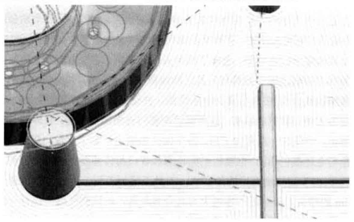
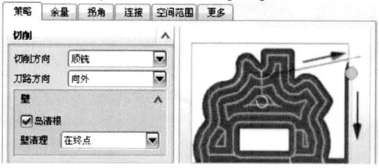
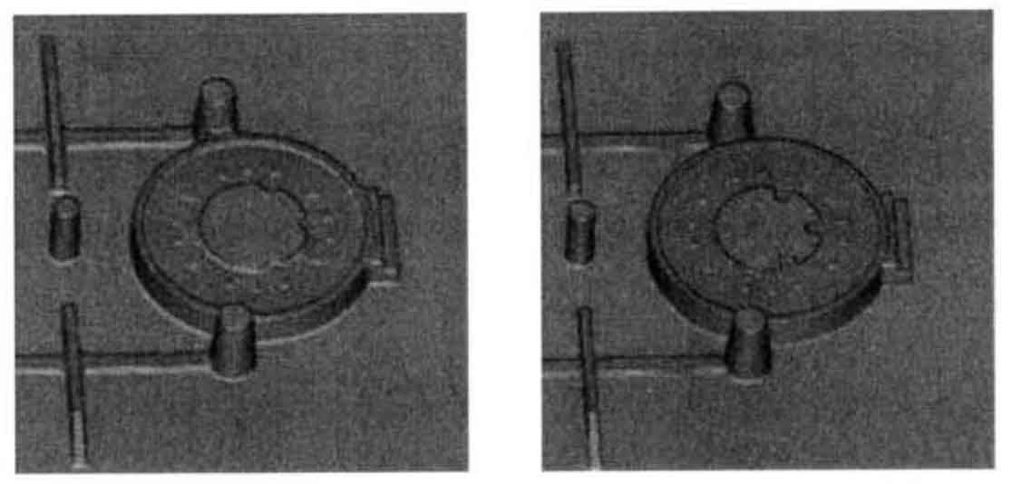
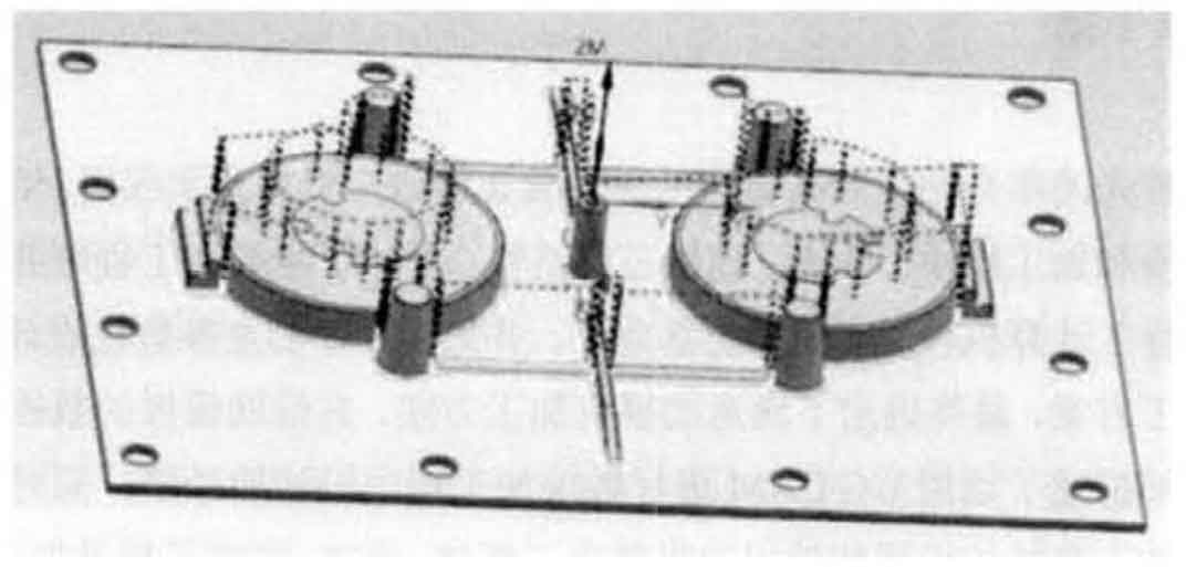
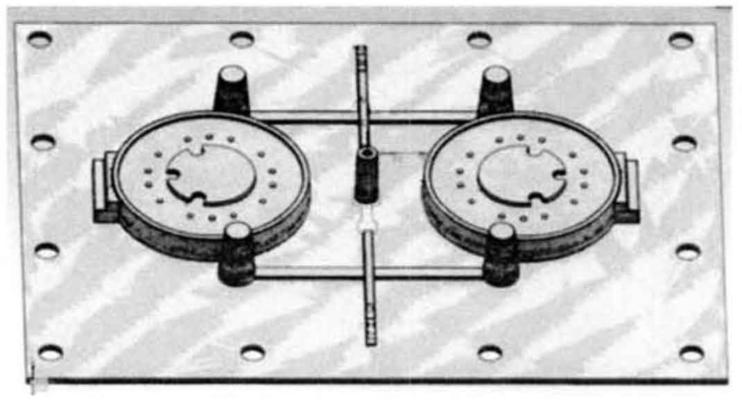
Finally, it enters the finishing stage of sand casting mold template, in which the part cutting allowance is set to zero. Create a flat head tool with diameter d = 12mm, select the area shown in Figure 1 A for plane milling, and the cutting mode is to follow the periphery, In this way, the tool path of this process intersects with the tool path of semi rough machining (because the finish machining tool path is very dense, in order to facilitate the display of the tool path style, the surface milling local tool path Figure 2 is used to display the effect picture of setting the cutting mode as the tool path after following the periphery), so as to improve the overall machining flatness of the surface of the sand casting mold template. Then create a flat head tool with diameter d = 6mm and select the area shown in Figure 1 B for plane milling. In each plane milling process during finish machining, during the setting of machining parameters, check wall cleaning and Island back cleaning in the drop-down menu of machining strategy setting to remove the residual blank allowance left by the cutting tool in the previous machining. The setting is shown in a in Fig. 3. In Fig. 3, B is a 2D simulation effect diagram of face milling in the same area for two times in order to clearly reflect the effect of this setting, deliberately increase the diameter difference of the tools used for two face milling, and only check the options of wall cleaning and island cleaning for the second time, After setting this option, the blank allowance of the wall edge of the upper plane of the sand casting and the structure around the “island” is cleared.
Next, finish the side contour of the sand casting mold template, create a tool with diameter d = 4mm and R = 0.2mm, and perform contour milling to complete the finish machining of the side wall of the sand casting mold template in the areas shown in a and B in Fig. 4.
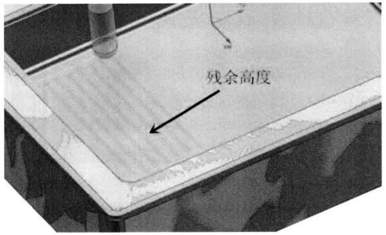
The tool paths of the above processes are similar to the corresponding tool paths in semi finishing. Only individual parameters have been changed, and the generated tool paths are more meticulous. In contour milling, the larger setting change is that the option of residual height is selected in the tool path setting – common depth of each tool drop-down option; The residual height here refers to the residual height between the tool and the tool in the process of two adjacent tool cutting, as shown in Fig. 5 is the 3D simulation cutting diagram of the residual height in the cutting of two adjacent tool paths. The maximum residual height is set to 0.01mm, which is also to make the tool path more meticulous and improve the surface processing quality of the side wall of the sand casting mold. The specific tool path diagram will not be displayed one by one. After this series of processing, each plane area meets the processing requirements, and its color is sand casting mold. The color of the mold components is alternating with the blank color. However, there is still a large blank margin at the side contour of the sand casting mold and the connection between the riser and the sand casting cavity. Due to the small draft angle of these sides, the cutting tools are not easy to process. Therefore, create a ball head tool with a diameter of D = 3mm, further increase the tool merging distance, and conduct another area contour milling for these areas. It is concluded that the sidewall results can meet the technical requirements of machining.
Finally, create a fixed shaft profile milling, select the driving mode as the root cleaning mode, and then create a tool with diameter d = SMM, bottom corner radius r = 0.2mm and a ball head tool with diameter d = 3.5mm respectively. The two cutters are used successively to carry out root cleaning for the whole part twice to remove the residual blank at the root of the side wall of the part. A in Fig. 6 is the tool path diagram of the second root cleaning treatment. So far, the whole sand casting mold template processing process is completed. Open the process navigator, select the top program of the project program and click generate. After all step-by-step processes are updated, the final 3D simulation effect diagram is shown in B in Figure 6. In the 3D effect color display, the blank color is alternating with the component primary color, which is caused by the display reason. Using the analysis function in the machining module, select several points on the plane to measure the geometric attributes, and the display allowance is 0. Due to the length of the article, the processing process of lower sand casting mold template will not be described in detail.
After updating all processes and accepting the tool path, the processing programming of sand casting mold template has been completed. Right click to select the project, select post-processing, set the output unit and other options, and click OK to automatically generate the NC processing program.


