
The finite element analysis of variable cross-section cast steel column bases designed by large steel castings manufacturer is aimed at solving the problems in the design and meeting the requirements of the “Steel Casting Code” that “for cast steel nodes without calculation formulas, finite element analysis is required to ensure the safety of the nodes”. Three typical section column bases are established with finite element models and their bearing capacity is analyzed.
1. Establishment of finite element model
Large scale steel castings manufacturer have established a total of four models for three typical cross-sectional column bases. Among them, column bases ZJ2 and ZJ3 only establish models of non penetrating cavities, while column base ZJ6 establishes models of non penetrating cavities and through cavities. The model takes a range of 1m below the bottom of the column to 1m above the top of the column, as shown in Figure 1 (a). Seamless steel pipes, cast steel parts, anchor bolts, and steel bars all adopt an ideal elastic-plastic model, and the yield strength is selected according to the tensile strength design values in the Steel Standard, Steel Casting Code, and Concrete Structure Design Code (GB50010-2010) (2015 edition) (referred to as the “Concrete Code”). The concrete adopts a plastic damage model, and specific parameters are selected according to Appendix C of the Concrete Code. Except for the use of T3D2 elements for steel reinforcement (which only consider axial forces and do not consider shear and bending moments), C3D8R elements are used for the rest, and the mesh division is shown in Figure 1 (b).
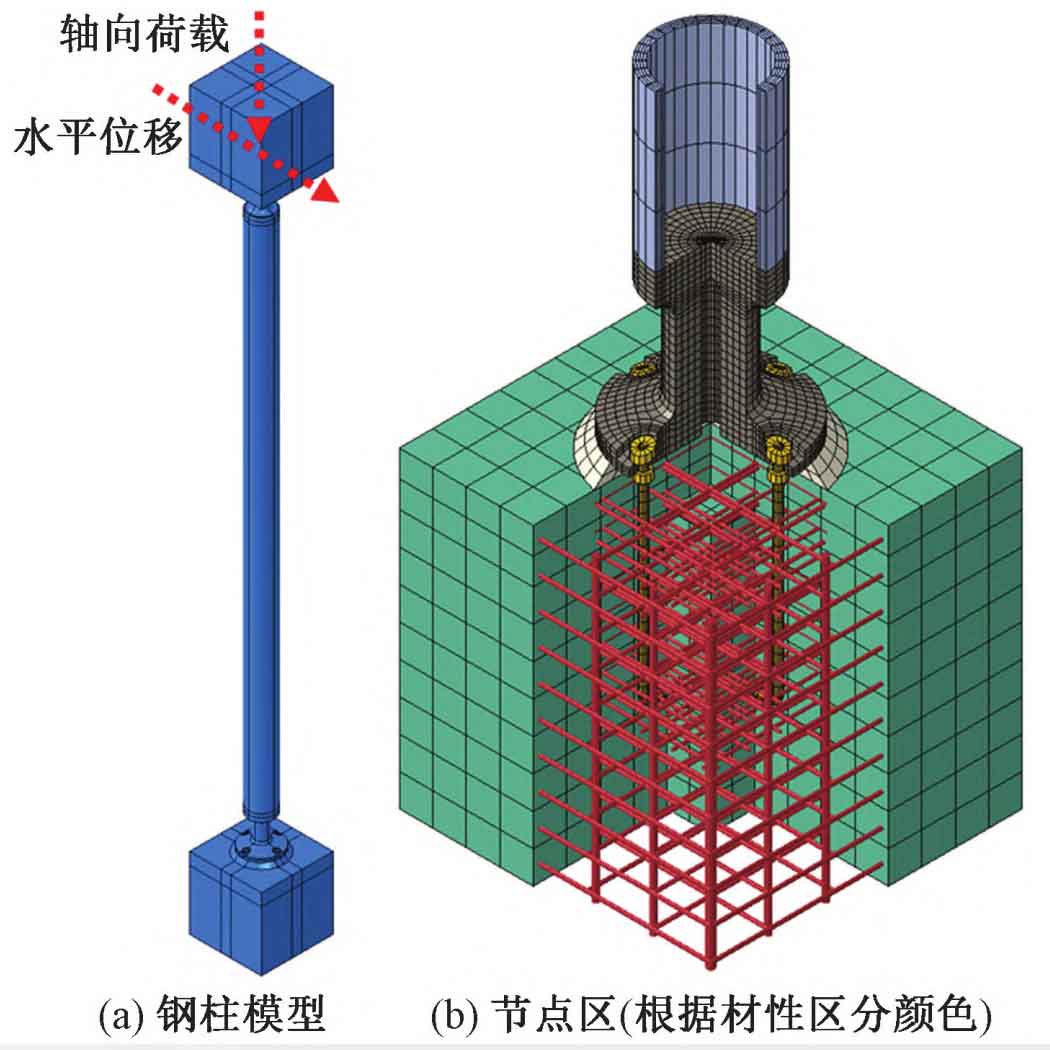
Large scale steel castings manufacturer use “hard” contact in the vertical direction and Coulomb’s friction model in the parallel direction in terms of contact definition. The friction coefficient between concrete and large steel castings is taken as 0 6. The friction coefficient between large steel castings and anchor bolts is taken as 0 3; The steel bars and anchor bolts are embedded in the concrete using an embedded constraint method. Set a reference point at 1m below the bottom of the column and 1m above the top of the column, coupling the concrete bottom to the reference point. Set the bottom reference point as a fixed connection; Constrain the horizontal displacement and all directional rotations for the top reference point.
When applying a load, first apply an axial load on the reference point at the top of the column, and the load size is taken as the maximum axial force design value; Due to the inability to determine the bending moment design value based on the overall model, displacement loads are applied at the reference point of the column top instead. The displacement value is the same as the interlayer displacement corresponding to the elastic interlayer displacement angle limit (1/1000) of reinforced concrete seismic wall structures in the “Code for Seismic Design of Buildings” (GB50011-2010) (2016 edition). The specific values of axial load and displacement load at the top of the column are shown in Table 1.
| Column base number | Axial force/kN | Total length of seamless steel pipes and cast steel parts/mm | Displacement load/mm |
| ZJ2 | 2 500 | 11 050 | 11 |
| ZJ3 | 5 300 | 11 050 | 11 |
| ZJ6 | 6 000 | 14 050 | 14 |
2. Analysis of node bearing capacity
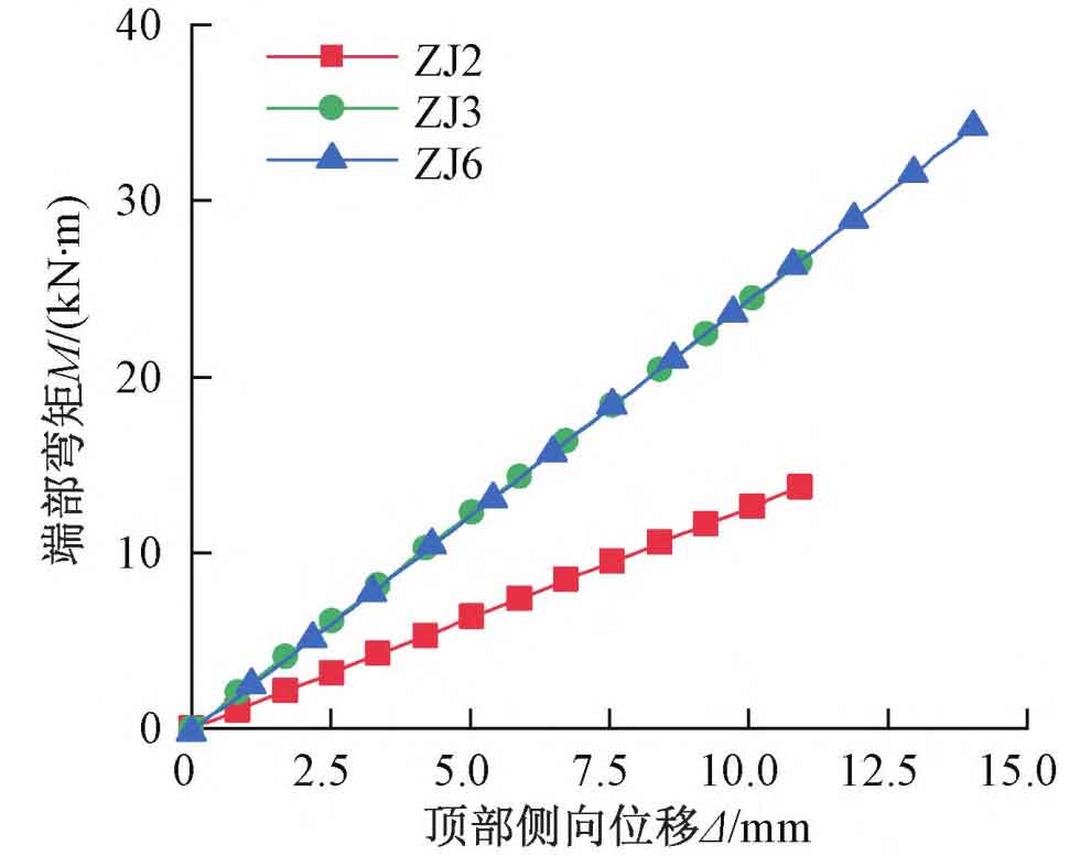
Large scale steel castings manufacturer designs bending moment M for each column base model with lateral displacement at the top Δ The changes are shown in Figure 2. As shown in the figure, within the specified displacement range, M varies with Δ The growth is linear with the increase of, and the nodes remain elastic.
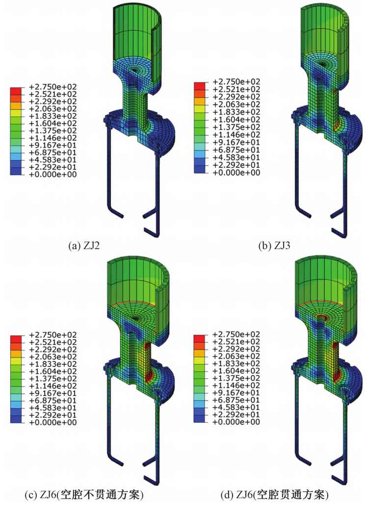
The von Mises stress cloud diagram for the ends of seamless steel pipes, steel castings, and anchor bolts designed by large-scale steel castings manufacturer is shown in Figure 3. As shown in the figure, the seamless steel pipes in each model are in an elastic state, and the anchor bolts are basically at a low stress level without yielding. The stress on the top tray of the column in Figure 3 (c) is much lower than the designed tensile strength value f=230MPa for large steel castings manufacturer, indicating that the force transmission of the top tray is not completely similar to that of the cantilever plate. By comparing Figures 3 (c) and (d), it can be seen that when the cavity penetrates, the stress around the top opening of the large steel casting designed by the manufacturer increases significantly. This is due to the interruption of the radial force transmission path on the surface of large steel castings designed by manufacturers due to the opening, resulting in significant circumferential tensile stress. Therefore, a non penetrating cavity scheme was chosen in subsequent designs.
Large scale steel castings manufacturer design steel castings where the stress is concentrated at the upper and lower neck chamfers. Among them, the von Mises stress of column base ZJ2 and ZJ3 under the design load is lower than the tensile strength design value of the steel casting, f=230MPa; The cast steel part of column base ZJ6 has a significant stress concentration at the upper and lower neck chamfers due to a sudden change in cross-sectional size, and the local stress exceeds the limit value of 230MPa. The first principal stress cloud map of column base ZJ6 is shown in Figure 4. It can be seen from Figure 4 that the first principal stress at the stress concentration point of column base ZJ6 is compressive stress. According to the Steel Casting Regulations, when all principal stresses at the calculation point are tensile stresses, the von Mises stress limit can be relaxed to 1 2f=276MPa, so the stress concentration area can still be considered elastic. The bearing capacity of the column base nodes of large steel castings designed by manufacturers meets the requirements of the Steel Casting Code.
The stress at the neck of the large steel casting designed by the manufacturer did not reach the tensile strength design value f under the specified displacement (the lateral displacement of the steel column in the overall model is less than the displacement in Table 1), indicating that the bending moment at the column base is less than the bending moment determined by the steel column fixation.


Figure 5 shows the Y-direction normal stress cloud map of column base ZJ6. Large steel castings manufacturer have a clear force transmission path from the column wall of the steel pipe to the neck of the cast steel, indicating that the axial force of the steel pipe is not solely transmitted to the neck of the large steel castings manufacturer’s designed cast steel, but is partially borne by the pressure in the direction of this force transmission path. Therefore, the bending moment at the root of the column top tray is significantly smaller than that calculated based on the cantilever plate, and the column top tray can meet the bearing capacity requirements according to the design size.
| Column base number | Uniformly distributed reaction force/MPa | Limit value of local compressive stress in concrete section/MPa | Axial force/kN | Local compressive bearing capacity/kN | Ratio |
| ZJ2 | 11.5 | 34.4 | 2 500 | 8 908 | 0.28 |
| ZJ3 | 24.5 | 49.1 | 5 300 | 11 036 | 0.48 |
| ZJ6 | 27.7 | 49.1 | 6 000 | 11 036 | 0.54 |
According to Figure 6, when the thickness of the base plate of the column is taken as 100mm, there is still a significant margin of bearing capacity. Taking the column base ZJ6 as an example, the stresses perpendicular to the plane of the bottom plate on the contact surface between the concrete foundation and the column base bottom plate are shown in Figures 7 and 8, respectively. From Figures 7 and 8, it can be seen that the reaction force of the concrete foundation on the column base is not uniformly distributed. In the design of large steel castings manufacturer, the stress in the corresponding area of the neck of the steel casting is relatively high and gradually decreases towards the surrounding area. The maximum compressive stress on concrete σ C=44 1MPa, approximately 1. of the uniformly distributed reaction force 1. 6 times in Table 2; σ C is less than the limit of compressive stress of concrete, which is 49 1MPa, meeting regulatory requirements. The compressive damage of the column base ZJ6 concrete is shown in Figure 9. It can be seen from the figure that under the specified load, there is no damage to the column base ZJ6 concrete.


