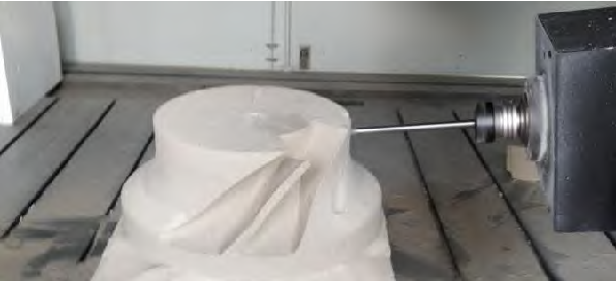
The experimental equipment is a digital five axis dieless casting precision forming machine developed by the General Institute of mechanical science, as shown in Figure 1. The equipment adopts servo motor to drive screw feed and PMAC controller. The main shaft adopts electric spindle with power of 8kw and maximum speed of 12000r / min. the cutter adopts special hollow end mill.
The measured pendulum length L is 403.70mm and the tool diameter is 10mm. Set the operation period of RTCP forward and inverse solution as 5ms, programming speed as f500, vector speed control mode, linear interpolation, spindle speed of 6000r / min. Start the forward and inverse calculation of RTCP, and carry out the experiment of five axis simultaneous forming of impeller sand mold. The five axis linkage machining process of impeller sand mold is shown in Fig. 2. The forming process is stable and the surface forming quality of sand mold is good.
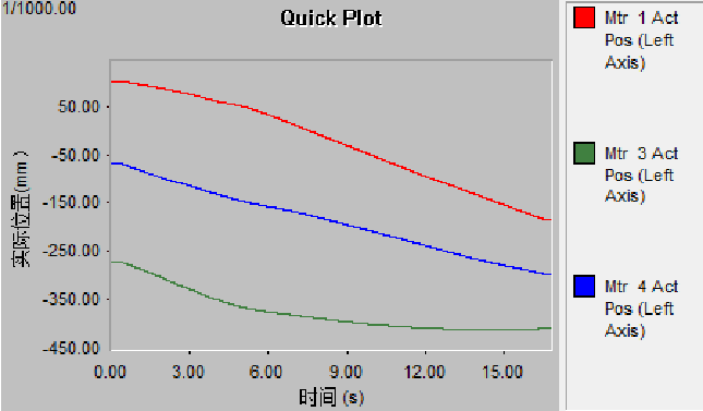
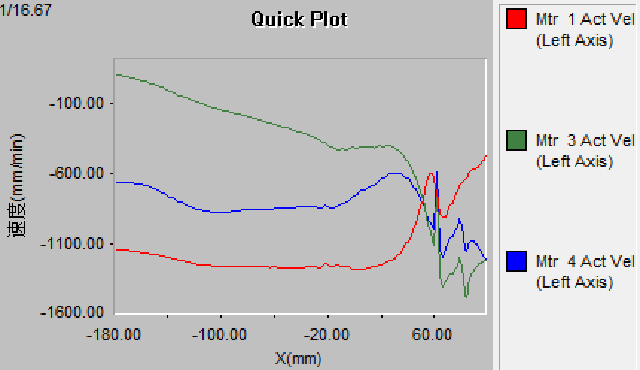
Using PMAC plot32pro data acquisition software of PMAC control system, the actual position curve of linear axis is shown in Fig. 3, in which mtr1, mtr3 and mtr4 correspond to x, y and Z respectively,.
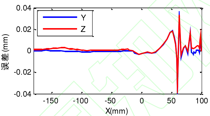
Taking X-axis position as abscissa, Y-axis and z-axis as ordinate, according to the method of linear difference, the simulation calculation of inverse solution position is compared with the actual operation of Figure 3, and the position error between operation and simulation calculation of controller RTCP is obtained, as shown in Figure 4.
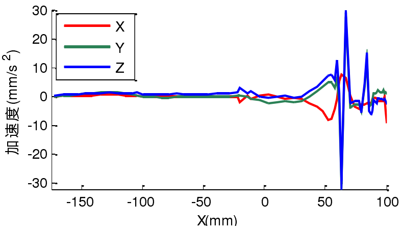
It can be seen from Fig. 4 that there is an error of -0.036mm in Y direction and -0.034mm in Z direction. According to the formula, calculate the speed change of the linear axis in the inverse solution of RTCP, divide it by the time interval shown in the formula to obtain the linear axis feed acceleration, as shown in Fig. 5. It can be seen that there is a linear relationship between the acceleration and the position of the RTCP. Because the x-axis feed acceleration is small, the maximum operation error of RTCP is the largest when the Y-axis and z-axis feed acceleration are maximum. It can be seen from the formula that the magnitude and variation range of acceleration of each feed axis depend on the contour characteristics of the workpiece, the swing length and the change of cutter shaft. In addition, the data sampling interval, RTCP calculation cycle, PID operation of each axis, feedback and other links also have a certain impact on the error size.
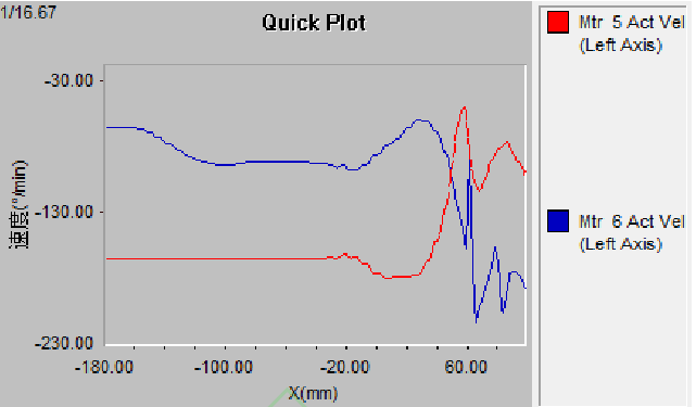
The linear axis speed and rotation axis speed in the processing process are collected, as shown in Fig. 6 and Fig. 7. Among them, the position of X axis is the abscissa, the velocity of each axis is the ordinate; mtr5 corresponds to axis C and mtr6 corresponds to axis B.