1. Simulation Model
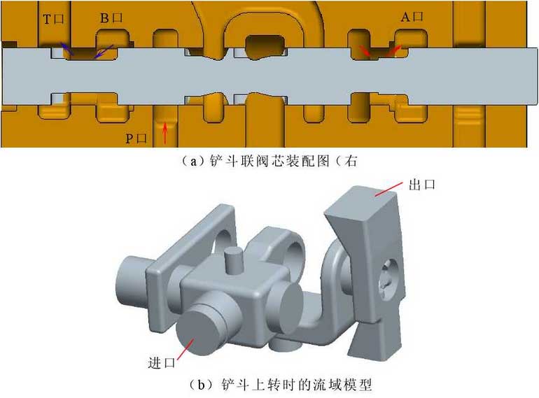
Fig. 1(a) shows the connection of each spool in the right position of the bucket union valve. The opening of the spool is 9.5mm. Pro/E is used to establish a three-dimensional model of the spool when it is working in the right position (bucket up-rotation condition).It can be seen from the diagram that different throttling edges have different throttling effects.The high pressure oil flows into the valve chamber, through the whole circumferential opening, through port A, and finally into the rodless chamber of the bucket cylinder. The cavity through which the oil flows is modeled as shown in Figure 1(b).
2 Grid Division
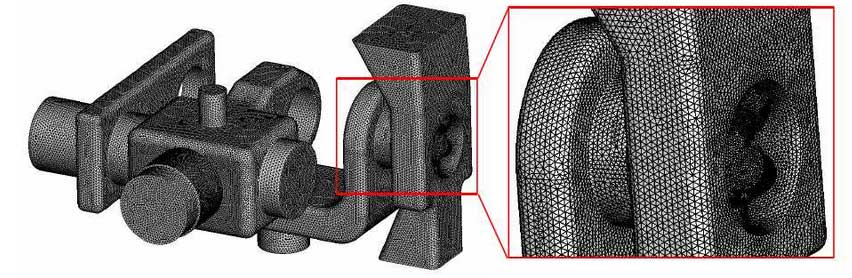
Gambit software is used to divide the watershed model under bucket running condition into grid, which adopts tetrahedral unstructured grid with strong adaptability.Because of the large oil velocity gradient, pressure drop and swirl state at the orifice, the local mesh is refined to ensure that there are at least five layers of mesh at the minimum size of the orifice.Finally, the meshing unit is 3.03 million and the quality is 0.89. The result of meshing is shown in Figure 2.
3.BOUNDARY CONDITIONS
The grid is imported into FLUENT to solve the numerical solution of fluid domain parameters.The turbulence model uses the standard k-e turbulence model; the density of oil is 860kg/m3, the dynamic viscosity is 0.03556kg/m.s, the thermal conductivity is 0.15W/m.K and the specific heat capacity is 293J/kg.K; the inlet boundary condition is pressure inlet 18MPa and the initial temperature is 27 degrees; the outlet boundary condition is pressure outlet 16MPa and the initial temperature is 27 degrees, and the convergence residuals are set at 10-60-66 degrees.
4.Analysis of simulation results of flow field
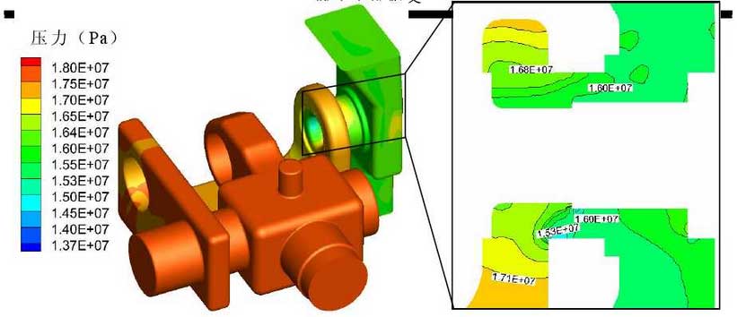
Figure 3 is a pressure distribution cloud diagram under the condition of bucket running upward. It can be seen from the diagram that the pressure of oil at the throttle port is relatively low, with a value of 15.3MPa, while the pressure behind the throttle port is relatively high, with a value of 16MPa. This is due to the throttling effect of the orifice when the oil flows through the valve port due to the abrupt decrease of the flow area.At the orifice, a large throttle loss is formed, while the pressure in other areas is relatively stable, which ultimately results in a small loss of resistance along the flow path and a large local loss.
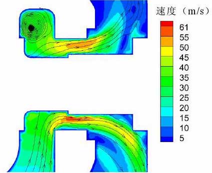
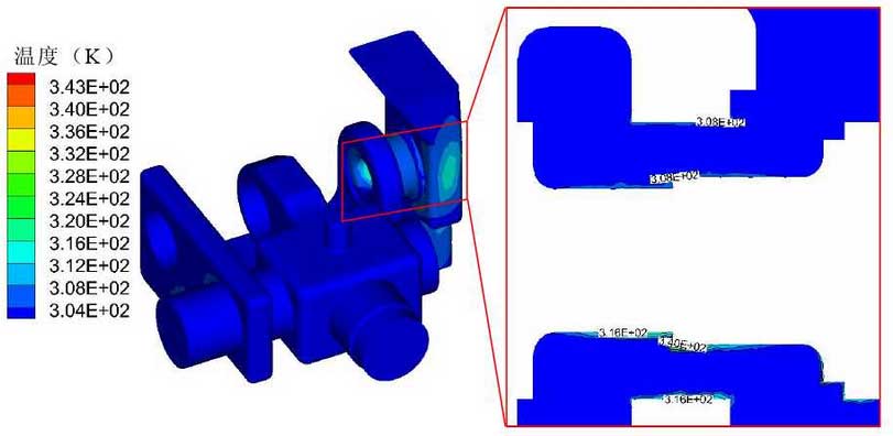
Figure 4 is a flow chart of the velocity at the throttle port section of the whole basin under the condition of bucket running upward. It can be seen from the chart that the velocity at the valve port can reach 61m/s. The throttling effect of the valve port makes the velocity gradient at the valve port larger. This is because the flow area reduces when the oil flows through the valve port, resulting in the increase of the velocity at the valve port; in addition, the velocity gradient ratio near the wall of the valve spool is higher.The velocity gradient near the valve body wall is larger, which is mainly due to the change of flow direction when the oil flows through the valve opening. Because of inertia, the oil will not change the flow direction immediately, but gradually changes the direction of movement during the operation, resulting in a greater velocity gradient near the spool wall than near the valve body wall.