
The precise simulation of the solidification process is a cornerstone of modern foundry engineering, enabling the prediction of defects and the optimization of processes for high-quality castings. At the heart of an accurate thermal simulation lies the definition of boundary conditions, among which the Interfacial Heat Transfer Coefficient (IHTC) between the casting and the mold is paramount. This parameter is not a fixed material property but a dynamic value that encapsulates the complex, evolving thermal contact at the interface. In metal die casting, the gap formation can sometimes be measured, but in the ubiquitous sand casting process, directly measuring the air gap between the sand mold and the solidifying metal is exceedingly difficult. The IHTC is influenced by a confluence of factors including the materials of the casting and mold, the casting geometry, and the process parameters. Therefore, obtaining reliable IHTC data specific to sand casting conditions is critical for enhancing the fidelity of Computer-Aided Engineering (CAE) simulations. This work presents a comprehensive experimental and numerical investigation to determine the IHTC for ZL101 aluminum alloy cast in resin-bonded sand molds, focusing on how the shape and dimensions of sand casting parts influence this crucial parameter.
Our investigation was structured around a series of carefully designed pouring experiments. We utilized ZL101 aluminum alloy as the casting material and furan resin-bonded sand for both the mold and cores. To understand the effect of geometry, we produced two fundamental types of sand casting parts: a flat plate and three concentric ring castings with varying dimensions. The specifications are summarized in the table below.
| Casting Type | Dimensions (Height x Width/Radii) | Notation |
|---|---|---|
| Flat Plate | 150 mm (H) x 150 mm (W) x 50 mm (Thickness) | Plate |
| Ring Casting Set 1 | 150 mm (H), Inner Radius (Rin)=30 mm, Outer Radius (Rout)=80 mm | R30/80 |
| Ring Casting Set 2 | 150 mm (H), Inner Radius (Rin)=50 mm, Outer Radius (Rout)=100 mm | R50/100 |
| Ring Casting Set 3 | 150 mm (H), Inner Radius (Rin)=70 mm, Outer Radius (Rout)=120 mm | R70/120 |
All molds were designed with a consistent mold thickness (sand fill) of 50 mm. The ZL101 alloy was melted and poured at a temperature of approximately 705°C. The core of the experimental setup was the strategic placement of K-type thermocouples to capture the transient temperature fields. For the plate casting, thermocouples were embedded in the casting (2 mm from the interface) and in the sand mold at distances of 6 mm, 14 mm, and 22 mm from the interface along the thickness direction. For the ring-shaped sand casting parts, thermocouples were placed similarly but along the radial direction for both the outer sand mold and the inner sand core. A multi-channel data recorder captured the temperature history throughout the solidification and cooling process.
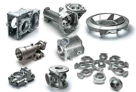
The fundamental challenge is that the IHTC cannot be measured directly. It must be inversely estimated from measurable quantities—in this case, the temperature histories within the sand mold or core. This is known as an Inverse Heat Conduction Problem (IHCP). We developed a mathematical model and a corresponding computational program in MATLAB to solve this IHCP. The approach is based on the following principles:
The heat transfer within the sand mold/core is assumed to be one-dimensional. For the plate, the direction is perpendicular to the interface (x-direction). For the ring sand casting parts, the direction is radial (r-direction). The governing transient heat conduction equation is:
$$ \rho(T) C_p(T) \frac{\partial T}{\partial t} = \frac{\partial}{\partial x} \left( k(T) \frac{\partial T}{\partial x} \right) $$
or in radial coordinates:
$$ \rho(T) C_p(T) \frac{\partial T}{\partial t} = \frac{1}{r} \frac{\partial}{\partial r} \left( r k(T) \frac{\partial T}{\partial r} \right) $$
where $\rho$ is density, $C_p$ is specific heat, $k$ is thermal conductivity, and $T$ is temperature. The thermal properties of the resin sand were treated as functions of temperature. The geometry of the ring sand casting parts requires special consideration. The sand mold and core were discretized using sector-shaped finite volume elements to account for the varying cross-sectional area along the radius. The energy balance for a general control volume $i$ leads to a discrete equation. For the first volume element adjacent to the interface, the equation incorporates the unknown interfacial heat flux, $q$. For a ring sand casting part’s outer mold, this equation is derived as:
$$ [1 + S_{out}(1)] T_1^{p+1} – S_{out}(1) T_2^{p+1} = T_1^p + S_q \cdot q^p $$
where $S_{out}(1)$ and $S_q$ are geometric and material coefficients, $T_i^p$ is the temperature of element $i$ at time step $p$, and $q^p$ is the average heat flux during the time step. For internal elements $i$ (from 2 to 5), the discrete equation is:
$$ -S_{in}(i)T_{i-1}^{p+1} + [1 + S_{in}(i) + S_{out}(i)]T_i^{p+1} – S_{out}(i)T_{i+1}^{p+1} = T_i^p $$
The boundary at the far end of the sand (element 6) is set to the measured temperature from the thermocouple located 22 mm from the interface. These equations form a tridiagonal system solvable by the efficient Thomas algorithm.
The core of the inverse solution is estimating the time-varying heat flux $q(t)$ at the interface. We employed Beck’s nonlinear estimation method. The heat flux history is discretized into piecewise constant steps, $q^p$. To stabilize the ill-posed inverse problem, the method uses information from “future” time steps. For estimating $q^p$, it is assumed constant for the next $r$ future steps ($q^p = q^{p+1} = … = q^{p+r-1}$). The objective is to find the $q^p$ that minimizes the sum of squared errors between the calculated and measured temperatures at the interior thermocouple locations (e.g., 6 mm and 14 mm from the interface) over the current and future $r$ time steps. This leads to an iterative correction formula for $q^p$:
$$ \Delta q = \frac{\sum_{n} \sum_{j=p}^{p+r-1} X_n^j (Y_n^j – T_n^j(q)) }{\sum_{n} \sum_{j=p}^{p+r-1} (X_n^j)^2 } $$
$$ q^{p}_{corrected} = q^{p}_{previous} + \Delta q $$
Here, $Y_n^j$ is the measured temperature, $T_n^j(q)$ is the temperature calculated using the current heat flux estimate, and $X_n^j$ is the sensitivity coefficient, defined as the derivative of temperature with respect to heat flux ($X_n^j = \partial T_n^j / \partial q^p$). The sensitivity coefficients are calculated by perturbing the heat flux by a small amount $\epsilon$ and computing the resulting temperature change via the direct model. This iterative correction continues until $|\Delta q / q^{p}_{corrected}|$ falls below a tolerance level. Once $q^p$ is determined, the corresponding IHTC, $h^p$, for that time interval is calculated using its macroscopic definition:
$$ h^p = \frac{q^p}{(T_{cast}^p – T_{mold,1}^p)} $$
where $T_{cast}^p$ is the measured casting surface temperature and $T_{mold,1}^p$ is the calculated temperature of the first sand element adjacent to the interface.
The analysis of the results reveals profound insights into the behavior of the IHTC for different sand casting parts. The interfacial heat flux, $q$, was highest at the very beginning of solidification due to the maximum temperature difference, then decayed over time. For the inner cores of ring sand casting parts, an interesting phenomenon was observed: after a certain time, the core temperature could exceed the casting temperature, causing a momentary reversal of heat flow (negative $q$), as the hot sand core reheated the solidified casting shell. This reversal occurred earlier for smaller cores (e.g., R30) due to their lower thermal mass.
The deduced IHTC values showed a characteristic and highly informative trend when plotted against the casting surface temperature, as summarized in the table below for key constant regions.
| Casting Part | Interface | Max IHTC (W/m²·°C) | Min IHTC (W/m²·°C) |
|---|---|---|---|
| Plate | Casting/Mold | ~108 | ~61 |
| Ring R80 | Casting/Outer Mold | ~131 | ~83 |
| Ring R100 | Casting/Outer Mold | ~127 | ~78 |
| Ring R120 | Casting/Outer Mold | ~103 | ~65 |
| Ring R30 | Casting/Inner Core | ~263 | ~144 |
| Ring R50 | Casting/Inner Core | ~183 | ~105 |
| Ring R70 | Casting/Inner Core | ~110 | ~75 |
The most significant finding is the “S-shaped” curve of IHTC versus temperature. The IHTC remains at a relatively high, constant value in the superheat region (above the liquidus). As solidification begins and proceeds between the liquidus and solidus temperatures, the IHTC drops sharply. This drop is directly linked to the formation and widening of an air gap at the interface caused by the casting’s solidification shrinkage and the mold’s thermal expansion. The IHTC eventually reaches a lower, nearly constant value in the solid cooling region (below the solidus), where the gap has largely stabilized.
The geometry of the sand casting parts dramatically affects the IHTC. Comparing the outer mold interfaces, the ring castings generally exhibited higher IHTC values than the flat plate. This is attributed to the constrained contraction of the ring, which hinders the uniform formation of a large air gap compared to the more free-contracting plate. Furthermore, among the ring sand casting parts, the IHTC at the outer mold interface increased as the outer radius decreased (e.g., R80 had a higher IHTC than R120).
The most striking geometric effect was observed at the inner core interface. Here, the IHTC was significantly higher than at the corresponding outer mold interface for the same casting. This is because the core, heated from the inside, expands outward while the casting shrinks away from it, potentially creating a tighter mechanical contact or a smaller gap. This effect is magnified for smaller cores; the R30 core exhibited an IHTC maximum (~263 W/m²·°C) more than double that of its outer mold. The “S-curve” for inner cores was also more prolonged, extending further into the solidus region, indicating a delayed and less severe gap formation process.
The validity of the inversely estimated IHTC was tested by using it as a boundary condition in a commercial CAE software (ProCAST) to simulate the solidification of a new ring sand casting part (Rin=60mm, Rout=110mm) not used in the inverse analysis. The simulated temperature history at a point within the casting was compared to the experimentally measured data. The results showed excellent agreement, with a maximum deviation of only about 17°C during the entire cooling process. This successful validation confirms the accuracy and reliability of the inverse methodology and the derived IHTC data. It demonstrates that implementing these geometry-dependent, temperature-varying IHTC curves, rather than a single constant value, can significantly improve the predictive accuracy of solidification simulations for complex sand casting parts.
In conclusion, this study provides a robust framework for determining the Interfacial Heat Transfer Coefficient in sand casting processes. The inverse methodology, combining targeted experiments with a sophisticated Beck algorithm-based solver, successfully captures the dynamic nature of the casting-mold thermal contact. The key outcome is the establishment of IHTC as a function of casting surface temperature, revealing a characteristic S-shaped curve primarily active during the solidification phase. Crucially, the research quantifies how the geometry of sand casting parts—specifically, whether the interface is with an outer mold or an inner core, and the associated radii—exerts a major influence on the magnitude and evolution of the IHTC. For instance, inner cores in ring-shaped sand casting parts can experience IHTC values significantly higher than outer molds or flat plates. These findings and the generated data are invaluable for foundry engineers and simulation specialists. By incorporating such detailed, geometry-aware IHTC boundary conditions into casting simulation software, the fidelity of predictions for solidification time, thermal gradients, and ultimately, the formation of shrinkage defects, can be greatly enhanced for a wide variety of industrial sand casting parts, leading to better first-time quality and reduced development costs.