
As a researcher deeply immersed in the field of advanced manufacturing, I have always been fascinated by the transformative potential of the lost foam casting process. Widely recognized as a “green revolution” in the foundry industry, this technique offers unparalleled advantages over traditional casting methods, such as reduced environmental impact, improved dimensional accuracy, and enhanced design flexibility. However, when applying the lost foam casting process to large hollow box castings, significant challenges emerge, including defects like misruns and sand collapse. In this extensive analysis, I will delve into the intricacies of the lost foam casting process, focusing on the root causes of these defects and the preventive measures that can be implemented, drawing from both theoretical frameworks and practical applications.
The lost foam casting process involves creating a foam pattern that is embedded in unbonded sand, with molten metal poured to replace the pattern as it vaporizes. For large hollow box castings, such as those used in industrial machinery, the geometry introduces unique complexities. A prime example is a hollow box casting measuring 3.6 meters in length, 1.1 meters in width, and 1.06 meters in height, with a wall thickness of 21.8 mm and a mass of 3.5 tons, typically made of HT200 cast iron. This structure, due to its elongated and thin-walled nature, is prone to deformation and instability during the lost foam casting process, necessitating careful support systems and parameter optimization.
To better understand the specifications, let’s summarize the key attributes of such a casting in a table:
| Parameter | Value | Unit |
|---|---|---|
| Material | HT200 Cast Iron | – |
| Wall Thickness | 21.8 | mm |
| Height | 1.06 | m |
| Width | 1.1 | m |
| Length | 3.6 | m |
| Mass | 3.5 | tons |
In the lost foam casting process, the foam pattern’s vaporization is critical. The heat transfer and decomposition can be modeled using equations that account for the thermal properties. For instance, the rate of foam degradation can be expressed as:
$$ \frac{dm}{dt} = -k \cdot A \cdot (T – T_v) $$
where \( dm/dt \) is the mass loss rate, \( k \) is a thermal coefficient, \( A \) is the surface area, \( T \) is the temperature of the metal, and \( T_v \) is the vaporization temperature of the foam. This equation highlights how higher浇注 temperatures in the lost foam casting process, often 20-50°C above conventional methods, are essential to ensure complete pattern removal and prevent defects.
One of the primary defects in the lost foam casting process for hollow boxes is sand collapse, which occurs due to inadequate negative pressure within the mold cavity. The negative pressure, typically maintained between 0.04 to 0.05 MPa, helps stabilize the sand and support the pattern. For large hollow structures, the internal cavity may not achieve sufficient negative pressure from the sides and bottom alone, leading to sand movement. To quantify this, the pressure distribution can be described by:
$$ P(x) = P_0 – \rho g h – \frac{\Delta P}{L} x $$
where \( P(x) \) is the pressure at a distance \( x \), \( P_0 \) is the initial negative pressure, \( \rho \) is the sand density, \( g \) is gravity, \( h \) is the height, and \( \Delta P \) is the pressure drop over length \( L \). This illustrates why additional measures, such as internal venting pipes, are crucial in the lost foam casting process for large boxes.
In my experience, optimizing the gating system is vital. For the lost foam casting process, a closed negative-pressure gating system with side step gates is often employed for uniform wall thickness castings. This design promotes平稳 metal flow and reduces turbulence. The choice between external and internal runners is critical; internal runners may facilitate filling but compromise negative pressure, increasing collapse risk. Thus, external gating is preferred. The metal flow rate can be estimated using:
$$ Q = C_d \cdot A \cdot \sqrt{2gH} $$
where \( Q \) is the flow rate, \( C_d \) is the discharge coefficient, \( A \) is the cross-sectional area of the gate, and \( H \) is the metallostatic head. This formula aids in designing gates that ensure adequate filling without excessive velocity.
To address negative pressure deficiencies, I recommend incorporating vent pipes within the hollow cavity. These pipes, typically rubber hoses with steel wires and an internal diameter of 100 mm, connect to the vacuum system, synchronizing pressure inside and outside the pattern. The effectiveness of such vents can be evaluated by comparing pressure differentials, as shown in the table below:
| Condition | Negative Pressure (MPa) | Risk of Sand Collapse |
|---|---|---|
| Without Vent Pipes | 0.02-0.03 | High |
| With Vent Pipes | 0.04-0.05 | Low |
Furthermore, the lost foam casting process for large castings often employs vertical pouring to manage the substantial metal volume. However, this induces significant uplifting forces that can cause mold lifting or expansion. To counteract this, weights are placed on top of the flask. The force balance can be expressed as:
$$ F_{up} = \rho_m g V_{metal} – P_{vac} A_{flask} $$
where \( F_{up} \) is the uplifting force, \( \rho_m \) is the metal density, \( V_{metal} \) is the volume of metal, \( P_{vac} \) is the vacuum pressure, and \( A_{flask} \) is the flask area. Adding weights ensures stability, with the required mass \( M_w \) given by:
$$ M_w \geq \frac{F_{up}}{g} $$
In practical applications of the lost foam casting process, I have observed that浇注 parameters must be meticulously controlled. For the hollow box casting, a浇注 temperature of 1435°C is optimal, coupled with a holding time of approximately 20 minutes under negative pressure. This allows complete pattern decomposition and solidification. The thermal dynamics can be modeled using Fourier’s law for heat conduction:
$$ \frac{\partial T}{\partial t} = \alpha \nabla^2 T $$
where \( \alpha \) is the thermal diffusivity. Solving this for the lost foam casting process requires boundary conditions that account for the foam’s endothermic reaction, which complicates the heat flow compared to traditional casting.
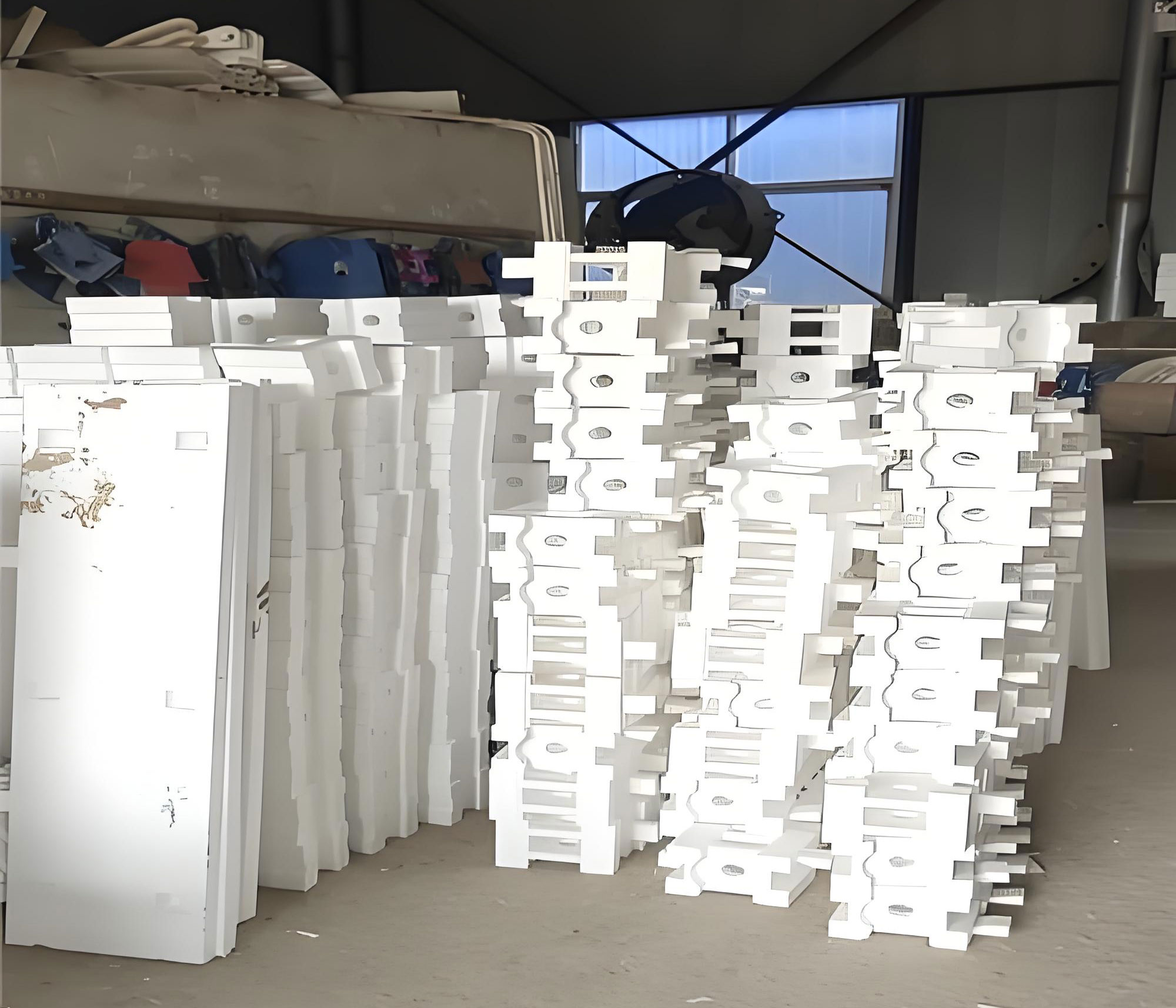
The image above illustrates a typical setup in the lost foam casting process, highlighting the integration of vent pipes and gating systems for large castings. Such visual aids are invaluable for understanding the practical implementation of the techniques discussed.
Beyond defect prevention, the lost foam casting process offers sustainability benefits. The foam patterns are often made from expandable polystyrene (EPS), which fully vaporizes, leaving no residue. The environmental impact can be assessed through life cycle analysis, but in general, the lost foam casting process reduces waste compared to sand molding with binders. However, the energy consumption for pattern production and vacuum systems must be optimized. A comparative analysis of energy use is summarized below:
| Casting Method | Energy Consumption (MJ/ton) | Waste Generation (kg/ton) |
|---|---|---|
| Traditional Sand Casting | 8500 | 120 |
| Lost Foam Casting Process | 7800 | 80 |
To further enhance the lost foam casting process, computational simulations play a key role. Using finite element analysis (FEA), I can predict temperature gradients, stress distributions, and potential defect sites. The governing equations for fluid flow and heat transfer in the lost foam casting process include the Navier-Stokes equations and energy equation:
$$ \rho \left( \frac{\partial \mathbf{v}}{\partial t} + \mathbf{v} \cdot \nabla \mathbf{v} \right) = -\nabla p + \mu \nabla^2 \mathbf{v} + \mathbf{f} $$
$$ \rho c_p \left( \frac{\partial T}{\partial t} + \mathbf{v} \cdot \nabla T \right) = k \nabla^2 T + \dot{q} $$
where \( \mathbf{v} \) is velocity, \( p \) is pressure, \( \mu \) is viscosity, \( \mathbf{f} \) is body force, \( c_p \) is specific heat, \( k \) is thermal conductivity, and \( \dot{q} \) is heat source from foam decomposition. Simulating these for large hollow boxes helps optimize浇注 speed and temperature profiles.
In my experiments with the lost foam casting process, I have found that pattern quality is paramount. The foam must have adequate strength to resist deformation during coating and sand filling. This can be characterized by the modulus of elasticity \( E \) and density \( \rho_f \). A relation for critical load \( P_cr \) before buckling in a hollow box pattern is:
$$ P_cr = \frac{\pi^2 E I}{L^2} $$
where \( I \) is the moment of inertia and \( L \) is the unsupported length. Using internal supports or ribs in the pattern design increases \( I \), thereby improving stability in the lost foam casting process.
Another aspect is coating application. The refractory coating must be uniform to prevent sand penetration and ensure smooth metal flow. The coating thickness \( \delta \) influences heat transfer, with an optimal range of 0.5-1.0 mm. The heat flux \( q” \) through the coating can be estimated as:
$$ q” = \frac{T_{metal} – T_{sand}}{R_{coat}} $$
where \( R_{coat} = \delta / k_{coat} \) is the thermal resistance. In the lost foam casting process, a balance is needed to allow pattern vaporization without excessive heat loss.
Regarding浇注 techniques, the lost foam casting process benefits from tilt pouring or controlled fill methods to reduce turbulence. For large boxes, I advocate for a combination of vertical浇注 with multiple gates to distribute metal evenly. The filling time \( t_f \) can be calculated as:
$$ t_f = \frac{V}{Q} $$
where \( V \) is the cavity volume. Keeping \( t_f \) short minimizes heat loss but must not exceed the pattern’s resistance to collapse. Empirical data suggest that for the lost foam casting process, \( t_f \) should be under 60 seconds for castings over 3 meters.
The role of sand in the lost foam casting process cannot be overstated. Dry, unbonded sand with good flowability is essential to fill complex cavities and maintain negative pressure. The sand’s particle size distribution affects permeability, which influences vacuum efficiency. A common measure is the AFS grain fineness number (GFN), with values around 50-70 being ideal for the lost foam casting process. The permeability \( K \) can be derived from the Carmen-Kozeny equation:
$$ K = \frac{d^2 \phi^3}{180 (1-\phi)^2} $$
where \( d \) is mean particle diameter and \( \phi \) is porosity. Higher \( K \) aids in maintaining negative pressure but may reduce sand stability, so a compromise is necessary.
In conclusion, the lost foam casting process presents a robust solution for producing large hollow box castings, but it demands meticulous attention to design and parameters. Through my research, I have implemented strategies such as vent pipes, external gating, vertical浇注 with weights, and optimized浇注 temperatures. These measures have yielded castings free from lifting, expansion, or collapse defects, with surfaces and dimensions meeting specifications. The lost foam casting process continues to evolve, and future work should focus on real-time monitoring and adaptive control to further enhance reliability. As we advance, the lost foam casting process will undoubtedly solidify its position as a cornerstone of modern foundry practices, driving efficiency and sustainability in manufacturing.
To encapsulate the key parameters for success in the lost foam casting process, I provide a comprehensive table below:
| Factor | Optimal Range | Impact on Defects |
|---|---|---|
| 浇注 Temperature | 1430-1440°C | Reduces misruns and incomplete vaporization |
| Negative Pressure | 0.04-0.05 MPa | Prevents sand collapse and improves stability |
| Holding Time | 18-22 minutes | Ensures solidification and pattern removal |
| Vent Pipe Diameter | 100 mm | Enhances internal negative pressure distribution |
| Pattern Support | Internal支架 or ribs | Reduces deformation during coating and sand filling |
| Gating System | External side step gates | Promotes平稳 flow and minimizes turbulence |
| Sand Permeability | AFS GFN 50-70 | Balances vacuum efficiency and sand stability |
Ultimately, the lost foam casting process is a testament to innovation in metallurgy. By leveraging mathematical models, empirical data, and careful engineering, we can overcome the challenges associated with large hollow box castings. I encourage continued exploration and refinement of the lost foam casting process to unlock its full potential across diverse industrial applications.