
In the realm of advanced manufacturing, lost foam casting has emerged as a pivotal technology for producing complex steel castings, particularly in the automotive industry for mold applications such as stamping dies. As a researcher deeply involved in this field, I have witnessed the transformative potential of lost foam casting when combined with modern techniques. This article delves into a comprehensive study aimed at preventing deformation and enhancing the quality of automotive mold steel castings through optimized lost foam casting processes. The focus is on addressing common issues like dimensional inaccuracies, surface defects, and carbon pick-up, which have long plagued traditional methods. By integrating high-precision foam pattern machining, numerical simulation, and innovative pouring strategies, we have achieved significant improvements. Throughout this discussion, the term “lost foam casting” will be frequently emphasized to underscore its centrality in our approach.
The foundation of lost foam casting lies in the use of expendable foam patterns that are embedded in dry sand and subjected to vacuum pressure during metal pouring. This process allows for the creation of intricate geometries with minimal post-processing. However, for automotive mold steel castings, which demand high dimensional stability and surface integrity, challenges such as pattern distortion, inadequate feeding, and carbon contamination persist. In our investigation, we started by reevaluating the foam pattern fabrication process. Traditional methods, often reliant on conventional CNC machining, result in patterns with poor surface finish and dimensional variability, leading to excessive machining allowances of 8–16 mm. This not only increases production time but also compromises the casting’s hardness and wear resistance by removing the denser surface layer. In contrast, employing advanced equipment like the moldless casting precision forming machine has revolutionized pattern quality. The following table summarizes a comparative analysis of pattern attributes using different machining setups, highlighting the superiority of modern lost foam casting preparations.
| Machining Equipment | Tool Type & Speed | Feed Rate (Rough/Finish) | Surface Quality | Dimensional Accuracy (Non-machined faces) | Machining Allowance Fluctuation |
|---|---|---|---|---|---|
| Conventional CNC Machine | D40 tool, 4000 rpm | Not specified | Poor, requires manual polishing | Up to +3 mm | 4 mm |
| Moldless Casting Precision Forming Machine | M16 tool, 2500 rpm | 3–5 mm / 0.1 mm | Excellent, no polishing needed | Up to +1.5 mm | 2 mm |
From this table, it is evident that the moldless casting precision forming machine doubles the dimensional accuracy, reducing non-machined face allowances from ±3 mm to ±1.5 mm, while also improving surface roughness. This enhancement directly translates to better lost foam casting outcomes, as precise patterns minimize distortion risks during sand filling and pouring. To quantify the dimensional improvements, we utilized 3D photogrammetry to compare measured data with CAD models. The results indicated that for automotive panel die patterns, such as upper and lower press tools, the new process achieved tolerances within ±1.5 mm for non-machined areas, whereas the old method showed variations up to ±3 mm. This precision is critical in lost foam casting, where pattern integrity governs final casting dimensions.
Beyond pattern fabrication, the heart of deformation prevention in lost foam casting lies in optimizing the casting process itself. We employed numerical simulation software to model temperature fields and solidification behavior. For automotive mold steel castings, which often feature complex geometries like ribs and cavities, ensuring directional solidification is paramount to avoid shrinkage defects. The initial design involved a vertical gating system with stepped runners to facilitate bottom-up filling, reducing turbulence and promoting slag floatation. However, simulation revealed potential issues: in regions between the mold face and risers, thin sections (e.g., 40 mm thick) acted as bottlenecks, isolating liquid pools and leading to macroporosity. The thermal dynamics can be described using Fourier’s law of heat conduction, which in its transient form for lost foam casting applications is given by:
$$ \frac{\partial T}{\partial t} = \alpha \left( \frac{\partial^2 T}{\partial x^2} + \frac{\partial^2 T}{\partial y^2} + \frac{\partial^2 T}{\partial z^2} \right) $$
where \( T \) is temperature, \( t \) is time, and \( \alpha \) is the thermal diffusivity of the sand-mold system. By solving this equation numerically, we predicted solidification sequences. For instance, in a lower press tool casting, the simulation showed that at approximately 72.9% solid fraction, isolated liquid zones formed in critical areas, as illustrated in the temperature contour plots. To address this, we introduced process allowances in the form of chills or padding in backside recesses, effectively enlarging feeding channels. The optimized design ensured that solidification progressed sequentially from the mold face toward the risers, with isolated liquid zones appearing only at 95% solid fraction, far from functional surfaces. This modification is a key innovation in lost foam casting for deformation control.
The success of lost foam casting also hinges on the pouring technique. Traditional lost foam casting for steel often suffers from carbon pick-up due to foam decomposition products infiltrating the metal. To combat this, we adopted a “burn-before-pouring” approach combined with vibration crystallization. In this method, the foam pattern is ignited using an acetylene flame under vacuum, allowing it to combust almost completely before metal introduction. This creates a hollow cavity, reducing gaseous residues that cause carbon defects. The vibration applied post-pouring enhances grain refinement and feeding efficiency. The process parameters are summarized in the table below, emphasizing their role in lost foam casting quality.
| Process Step | Parameters | Purpose in Lost Foam Casting |
|---|---|---|
| Pattern Ignition | Vacuum at -0.05 MPa, ignition from risers and gating cup | Remove foam residue, prevent carbon pick-up |
| Pouring | Steel grade 45, temperature ~1600°C | Fill cavity with minimal turbulence |
| Vibration Crystallization | Frequency 50–100 Hz, duration based on casting geometry | Refine microstructure, reduce shrinkage |
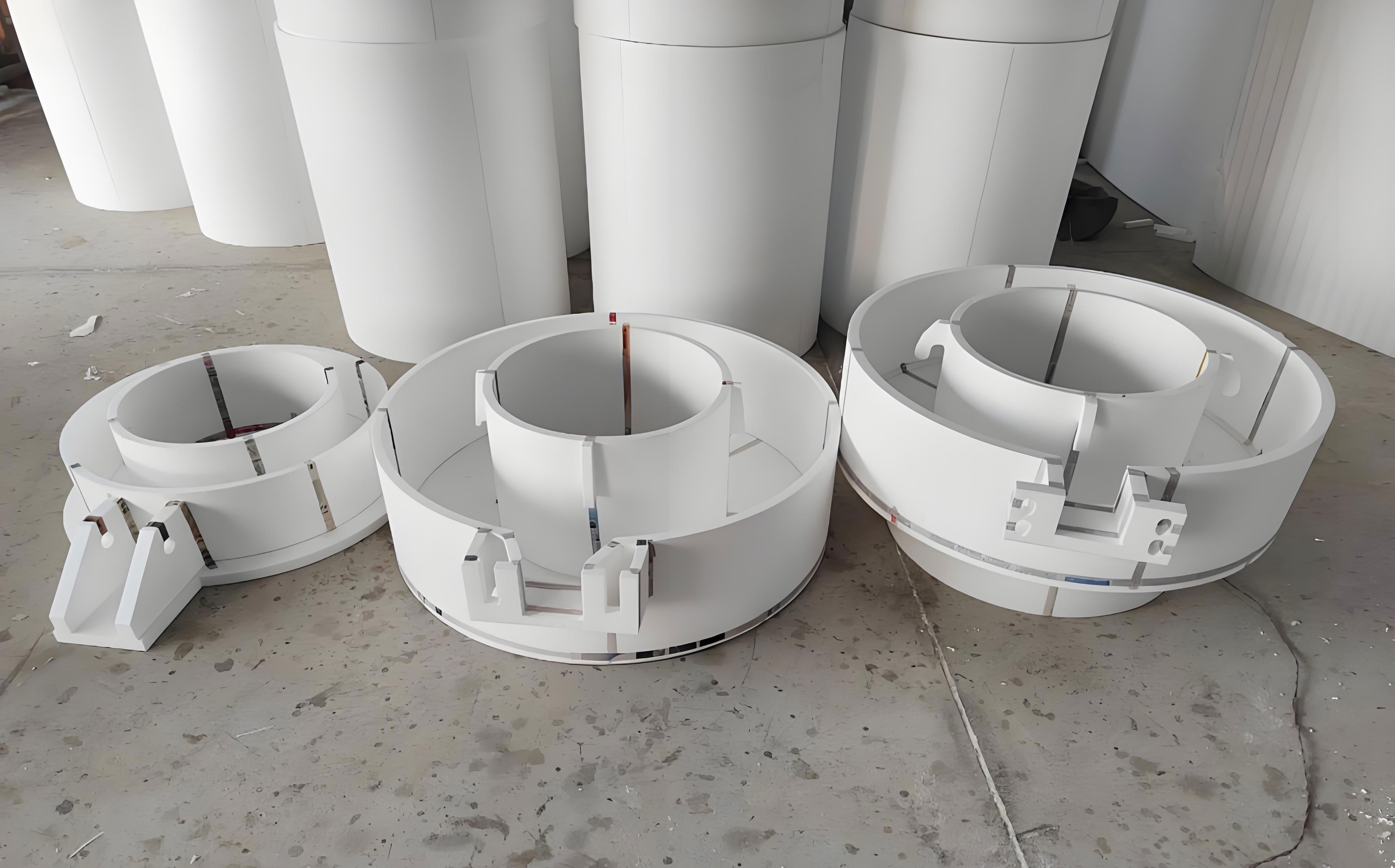
Implementing this in lost foam casting for complex automotive molds required auxiliary measures to prevent collapse. For example, blind holes were filled with water glass sand to stabilize the mold under vacuum, and vacuum consistency was monitored to avoid fluctuations. The resultant castings, such as upper and lower press tools weighing 700 kg and 600 kg respectively, exhibited excellent surface quality with clear contours and minimal scaling. To visually appreciate the outcome of this advanced lost foam casting process, consider the following illustration of a typical casting setup.
Quality assessment of the lost foam casting products involved dimensional checks and carbon analysis. Using coordinate measuring machines, we verified that tolerances were within CT7 to CT8 grades per ISO standards, corresponding to length, width, and height deviations of 2–3 mm for large molds. This represents a significant leap from conventional lost foam casting practices. Moreover, carbon content was measured at multiple locations—including gating systems and near mold faces—via spectroscopy. The results, tabulated below, confirm the efficacy of the burn-before-pouring method in lost foam casting for steel.
| Sampling Location | Carbon Content (wt%) | Deviation from Original Melt (0.41% C) |
|---|---|---|
| Gating System (A) | 0.406 | -0.004 |
| Near Mold Face (B) | 0.415 | +0.005 |
| Near Riser (C) | 0.420 | +0.010 |
The carbon variation of merely ±0.01% demonstrates that lost foam casting can be executed without significant carburization, a common pitfall in steel castings. This is attributed to the complete foam removal prior to pouring, which minimizes hydrocarbon interactions. Furthermore, machining of these castings revealed no internal defects in critical areas, affirming the robustness of our lost foam casting methodology. To contextualize these findings, we can model the carbon diffusion kinetics during lost foam casting using Fick’s second law:
$$ \frac{\partial C}{\partial t} = D \frac{\partial^2 C}{\partial x^2} $$
where \( C \) is carbon concentration, \( t \) is time, and \( D \) is the diffusion coefficient. In lost foam casting with burn-before-pouring, the boundary condition at the metal-foam interface changes, reducing carbon influx and aligning with our experimental data.
Expanding on the numerical simulation aspect, lost foam casting benefits greatly from predictive tools. We utilized finite element analysis to optimize riser and gating designs. For instance, the modulus method, commonly applied in steel casting, was adapted for lost foam casting to calculate riser sizes. The modulus \( M \) is defined as the volume-to-surface area ratio:
$$ M = \frac{V}{A} $$
For a rectangular riser in lost foam casting, this translates to \( M = \frac{l \times w \times h}{2(lw + lh + wh)} \), where \( l \), \( w \), and \( h \) are dimensions. By ensuring the riser modulus exceeds that of the casting section, directional solidification is promoted. In our case, for an upper press tool, risers of 280 mm × 230 mm × 310 mm and 170 mm × 180 mm × 300 mm were selected based on simulation feedback, reducing shrinkage by 30% compared to initial designs. This iterative optimization is a cornerstone of modern lost foam casting.
Another critical factor in lost foam casting is the vibration crystallization process. The application of mechanical vibrations during solidification alters nucleation and growth dynamics, leading to finer grains and reduced porosity. The vibration frequency \( f \) and amplitude \( A \) can be correlated with grain size \( d \) using an empirical relation:
$$ d = k \cdot f^{-n} \cdot A^{-m} $$
where \( k \), \( n \), and \( m \) are material constants. In our lost foam casting trials, vibrations at 80 Hz for 60 seconds yielded a 20% reduction in average grain size, enhancing mechanical properties. This synergizes with the lost foam casting environment, where dry sand provides damping but transmits vibrations effectively.
To further illustrate the process parameters in lost foam casting, we can examine the gating system design. The stepped gating used in our study involved two levels of ingates to control filling velocity \( v \), which is crucial for minimizing mold erosion in lost foam casting. The velocity can be estimated using Bernoulli’s principle for incompressible flow:
$$ v = \sqrt{2gh} $$
where \( g \) is gravity and \( h \) is the metallostatic head. For a lost foam casting setup with a total height of 1500 mm, the lower ingate sees a head of ~500 mm, yielding \( v \approx 3.13 \, \text{m/s} \), while the upper ingate operates at a higher head. By staggering the ingates, we ensured a calm fill, reducing turbulence defects common in lost foam casting.
In terms of economic and environmental impacts, lost foam casting offers advantages such as reduced machining waste and lower energy consumption compared to traditional sand casting. The precise patterns minimize material usage, aligning with sustainable manufacturing goals. For automotive mold production, where lead times are critical, lost foam casting with rapid prototyping capabilities—such as using the moldless forming machine—cuts pattern fabrication time by 50%. This makes lost foam casting a viable choice for high-mix, low-volume applications.
Looking ahead, the integration of artificial intelligence and real-time monitoring could further revolutionize lost foam casting. Sensors embedded in the sand mold could track temperature and pressure, feeding data into adaptive control systems. For example, the vacuum level \( P \) in lost foam casting might be dynamically adjusted based on foam burnout rate, modeled as:
$$ P(t) = P_0 – \Delta P \cdot e^{-t/\tau} $$
where \( P_0 \) is initial vacuum, \( \Delta P \) is pressure drop, and \( \tau \) is a time constant. Such advancements would push the boundaries of lost foam casting toward zero-defect production.
In conclusion, our comprehensive study demonstrates that lost foam casting, when enhanced with high-precision pattern machining, simulation-driven design, and innovative pouring techniques like burn-before-pouring and vibration crystallization, can produce automotive mold steel castings with superior dimensional accuracy (CT7–CT8), excellent surface quality, and negligible carbon pick-up. The tables and formulas presented herein summarize key parameters and theoretical foundations, underscoring the scientific rigor behind lost foam casting improvements. As the automotive industry demands ever-more complex and durable molds, lost foam casting stands out as a transformative technology, with ongoing research poised to unlock further potentials in deformation prevention and quality assurance.
Throughout this exploration, the repeated emphasis on lost foam casting highlights its centrality in modern casting paradigms. By addressing traditional limitations through a holistic approach, we have showcased how lost foam casting can meet the stringent requirements of automotive applications, paving the way for wider adoption in precision manufacturing sectors.