
In the relentless pursuit of automotive lightweighting, the adoption of advanced manufacturing processes for aluminum alloys is paramount. Among these, low-pressure casting (LPC) stands out for its ability to produce high-integrity, complex, and thin-walled components that are often challenging for conventional gravity casting. This article details a comprehensive methodology for the process and die design of a critical thin-walled aluminum shell casting for automotive applications. My focus is on the systematic calculation of key process parameters and the precise engineering of the die, utilizing modern design tools to ensure manufacturability and performance.
The component in question is a structural housing or shell casting, typically used in transmission or engine-related assemblies. Its primary function often involves enclosing mechanisms while providing mounting points, leading to a geometrically complex design. The defining characteristics of such shell castings include relatively large planar surfaces, varying wall thicknesses, integrated flanges, and numerous through-holes or bosses for assembly. Successful production requires a process that offers controlled filling and directional solidification under pressure. This is where low-pressure casting excels. The process involves pressurizing a sealed furnace, forcing molten metal up a refractory tube (stalk) into a die cavity positioned above. The pressure is maintained until the casting solidifies, after which it is released, and the cycle repeats. The principal advantages for shell castings are excellent metal yield, reduced turbulence and oxide formation, and superior mechanical properties due to pressure-assisted feeding.
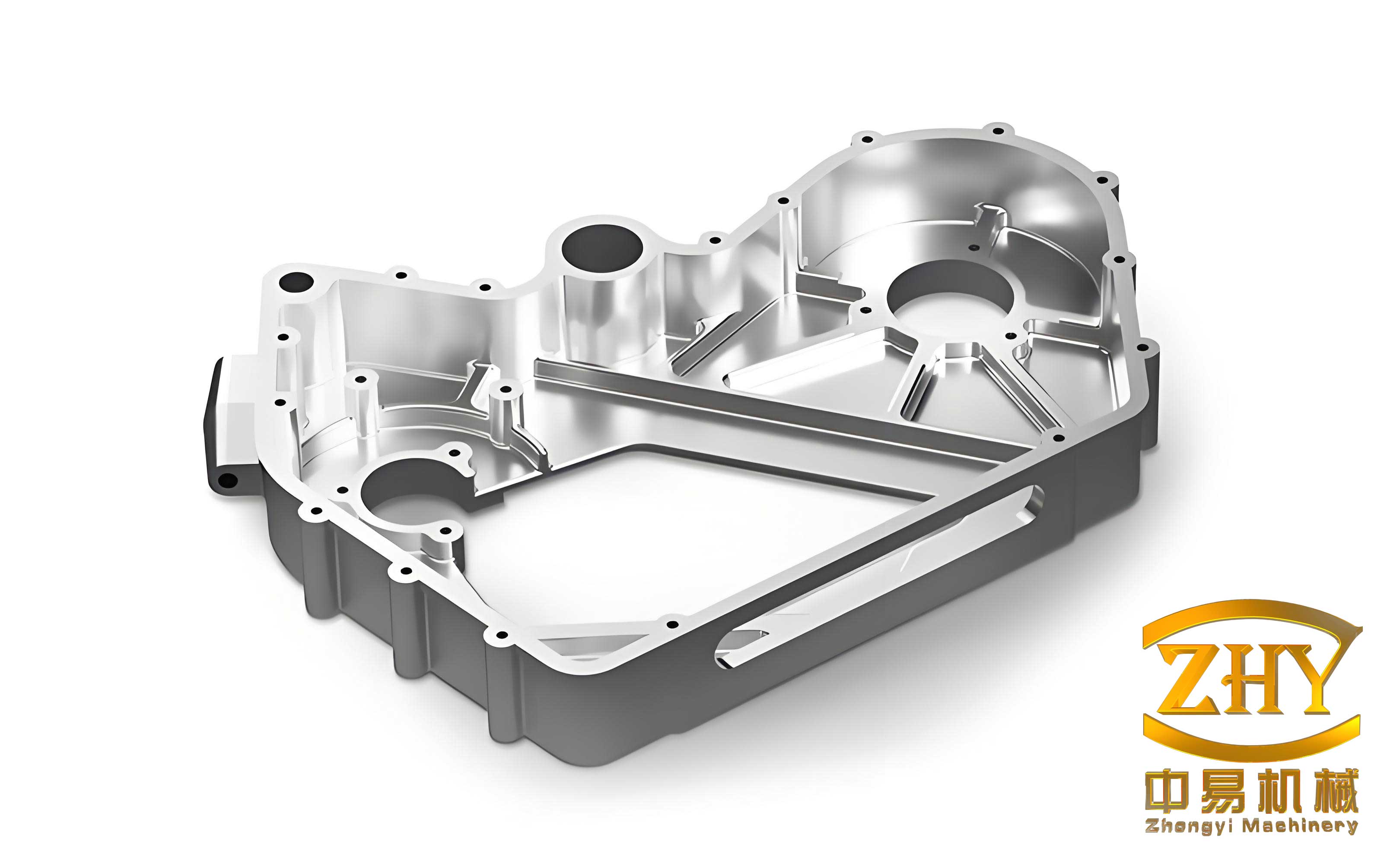
The specific aluminum shell casting analyzed here has an average wall thickness of approximately 5 mm, fabricated from a high-strength cast aluminum alloy (e.g., A356 or similar). The geometry features a main body with a deep drawn shape, side flanges with bolt patterns, and several peripheral holes. The inherent thin-walled nature and the presence of both internal and external geometric features make die design and part ejection non-trivial. A detailed structural analysis is the first step, identifying the thickest sections (hot spots) for feeding and the thinnest sections to ensure fillability. The table below summarizes a comparative analysis of casting processes for such components.
| Process | Typical Wall Thickness (mm) | Surface Finish | Mechanical Properties | Suitability for Complex Shell Castings |
|---|---|---|---|---|
| Sand Casting | > 4-5 | Rough | Standard | Moderate (poor detail) |
| High-Pressure Die Casting | 0.8-3.0 | Excellent | Good (can have porosity) | High (but for high volume) |
| Low-Pressure Casting | 3.0-10.0 | Very Good | Excellent (dense) | Very High (optimal balance) |
| Gravity Permanent Mold | > 4-5 | Good | Good | Moderate (filling issues for thin walls) |
The heart of a robust low-pressure casting process lies in the precise definition and control of the pressure-time profile. This profile dictates the metal velocity during different stages of the cycle: lift, filling, intensification, and solidification. Let’s break down the calculation for each critical parameter.
1. Process Parameter Design and Calculation
1.1 Gating and Feeding Philosophy
For a shell casting, the gating system is typically simple. The stalk itself acts as the primary sprue. The goal is to position the inlet(s) at the bottom of the die cavity, ideally beneath a heavy section to promote thermal gradient for directional solidification towards the stalk, which acts as a live feeder. The cross-sectional area of the gate should be sized to be slightly larger than the thermal hot spot it feeds but smaller than the stalk exit area to maintain a slight choke and prevent premature freezing. For the example housing, a single central gate at the bottom is often optimal.
1.2 Lift Phase Pressure and Velocity
The lift pressure (P1) is the pressure required to raise the molten metal from the furnace bath level to the gate entrance at the bottom of the die. It is a function of the metallostatic head and system friction.
$$P_1 = \rho g H_1 \mu$$
Where:
$\rho$ = Density of molten alloy at pouring temperature (approx. 2400 kg/m³ for Al-Si alloys at 700°C).
$g$ = Acceleration due to gravity (9.81 m/s²).
$H_1$ = Effective lift height from bath surface to gate (m). This increases as metal is drained from the furnace.
$\mu$ = Friction resistance coefficient (typically 1.0 – 1.5).
The lift velocity (vlift) is critical. Too fast, and metal will jet into the cavity, causing turbulence; too slow, and premature freezing can occur in the stalk. An optimal range is 40-80 mm/s. The velocity is controlled by the rate of pressure increase (dP/dt) in the furnace. The relationship between pressure and fill height in the stalk is derived from the equilibrium equation:
$$P(t) = \rho g H(t) \mu$$
Differentiating with respect to time gives the required pressure ramp rate for a desired lift speed:
$$\frac{dP}{dt} = \rho g \mu \frac{dH}{dt} = \rho g \mu \cdot v_{lift}$$
1.3 Filling Phase Pressure and Velocity
Once metal enters the die cavity, the filling phase begins. The required pressure increases as the metal column grows. The maximum filling pressure (Pfill) is needed when the cavity is completely filled to its topmost point.
$$P_{fill} = \rho g H_{total} \mu$$
Where $H_{total}$ is the total height from the bath surface to the top of the casting cavity.
The filling velocity (or cavity fill rate) must be tailored to the casting geometry. Thin-walled shell castings require faster filling to avoid mistruns, while thicker sections can be filled more slowly. This is controlled by the post-lift pressure ramp rate. A common approach uses a two-stage ramp, as conceptualized in the pressure-time curve. The table below summarizes the calculation steps for key pressures.
| Parameter | Symbol | Formula | Example Calculation (for H1=0.3m, Htotal=0.8m) |
|---|---|---|---|
| Lift Pressure | P1 | $P_1 = \rho g H_1 \mu$ | $P_1 = 2400 \times 9.81 \times 0.3 \times 1.3 \approx 9.18 \text{ kPa}$ |
| Max Fill Pressure | Pfill | $P_{fill} = \rho g H_{total} \mu$ | $P_{fill} = 2400 \times 9.81 \times 0.8 \times 1.3 \approx 24.48 \text{ kPa}$ |
| Pressure Ramp for Lift (v=0.06 m/s) | dP/dtlift | $\frac{dP}{dt} = \rho g \mu \cdot v_{lift}$ | $\frac{dP}{dt} = 2400 \times 9.81 \times 1.3 \times 0.06 \approx 1.84 \text{ kPa/s}$ |
1.4 Intensification (Crystallization) Pressure and Holding Time
Immediately after filling, the pressure is rapidly increased to a higher level known as the intensification or crystallization pressure (Pcryst). This pressure is maintained throughout the solidification of the shell casting and is crucial for feeding shrinkage porosity and ensuring density. The required pressure can be estimated based on the feeding distance needed and the alloy’s solidification characteristics. A common rule of thumb is to apply an additional 0.2 to 0.5 bar (20 to 50 kPa) over the fill pressure.
$$P_{cryst} = P_{fill} + P_{intensification}$$
For thin-walled aluminum shell castings, an intensification pressure of 30-50 kPa is often sufficient, as solidification is rapid.
The holding time (thold) is the duration for which the intensification pressure is applied. It must be long enough for the entire casting, especially the thickest sections, to solidify sufficiently so that the “feed path” back to the stalk is closed. Releasing pressure too early causes “back suction,” creating shrinkage cavities. Holding too long makes the stalk connection overly thick and difficult to remove. It is empirically determined, often as a function of the modulus (Volume/Surface Area) of the heaviest section. For a 5-mm average wall shell casting in a metal die, holding times typically range from 45 to 120 seconds. A simplified empirical relation is:
$$t_{hold} \approx k \cdot M^n$$
Where $M$ is the modulus of the main hot spot (in cm), $k$ is a coefficient dependent on alloy and die material (~100-300 for Al in metal die), and $n$ is an exponent often between 1.5 and 2.
1.5 Thermal Parameters: Pouring and Die Temperature
The thermal regime is vital for surface quality and soundness. The pouring temperature (Tpour) must ensure complete filling without excessive turbulence or gas pickup. For thin-walled aluminum shell castings, it is typically 10-30°C above the alloy’s liquidus temperature. The die temperature (Tdie) controls the solidification rate and heat extraction balance. A pre-heated die (150-250°C) is essential for metal dies to prevent cold shuts, reduce thermal shock, and promote controlled solidification. For our 5-mm shell casting, a die temperature of 200±20°C is a robust starting point.
The governing equation for heat transfer during initial contact is complex, but the initial heat flux (q) can be approximated by:
$$q = h (T_{pour} – T_{die})$$
Where $h$ is the interfacial heat transfer coefficient, which is very high at the moment of metal impact.
2. Die Design for Shell Castings
The die must withstand thermal cycling, facilitate filling and solidification, allow for part ejection, and ensure dimensional accuracy. The design process is iterative and involves structural, thermal, and mechanical considerations.
2.1 Die Structure and Parting Planes
The complex geometry of a shell casting often necessitates multiple parting planes. The primary parting plane is usually horizontal, splitting the die into cope and drag. However, to form external undercuts or deep draws, vertical side cores (slides) are required. For the housing example, a three-part die structure is logical: a left die half, a right die half (both moving vertically or horizontally as slides), and a central core that forms the internal cavity. This allows the casting to be extracted after retracting the side cores. The die structure must be rigid, with sufficient guide pins and locking mechanisms to resist metal pressure.
2.2 Cavity Dimension Calculation
Die cavity dimensions are not equal to the final part dimensions. They must account for the total contraction of the casting alloy from solidification to room temperature, as well as the expansion of the die material itself when heated to operating temperature. The fundamental formula for a cavity dimension ($d_c$) to produce a desired casting dimension ($d_p$) is:
$$d_c = d_p \cdot (1 + \epsilon_{net})$$
Where the net shrinkage factor $\epsilon_{net}$ is a combination of alloy shrinkage and die expansion:
$$\epsilon_{net} = f \cdot [\alpha_{cast} – (\alpha_{die} \cdot \Delta T_{die})]$$
Here:
$\alpha_{cast}$ = Linear shrinkage of the aluminum alloy (typically ~1.1% or 0.011 for Al-Si).
$\alpha_{die}$ = Coefficient of thermal expansion (CTE) of the die steel (e.g., 14.7 x 10⁻⁶ /°C for H13 steel).
$\Delta T_{die}$ = Temperature increase of the die cavity surface from ambient to operating temperature (e.g., 200°C – 20°C = 180°C).
$f$ = Restriction factor (0 ≤ f ≤ 1), accounting for mechanical hindrance to shrinkage; for shell castings with cores, f can be 0.8-0.9.
Example calculation for a nominal 100 mm diameter:
$\epsilon_{net} = 0.85 \cdot [0.011 – (14.7 \times 10^{-6} \times 180)] \approx 0.85 \cdot [0.011 – 0.002646] \approx 0.0071$
$d_c = 100 \cdot (1 + 0.0071) = 100.71 \text{ mm}$
2.3 Die Wall Thickness and Thermal Management
Die wall thickness is a compromise between mechanical strength (to resist distortion under pressure) and thermal performance (heat extraction rate). Excessively thick walls slow down cycle time; thin walls may warp. A common empirical rule for aluminum low-pressure casting dies is to make the wall thickness 3 to 4 times the local casting wall thickness, with a minimum absolute thickness for structural integrity. For our 5-mm shell casting, a die wall thickness of 20-25 mm in critical areas is common, with massive backing blocks of 100-150 mm to provide overall rigidity. Active thermal management via heating/cooling channels is essential to maintain the target die temperature profile. These channels are placed following the rule of thumb: their distance from the cavity surface should be 1.5-2.5 times their diameter, and the pitch between channels should be 3-5 times their diameter.
2.4 Core Design and Ejection
Cores for metal dies can be fixed or movable. The internal shape of a shell casting is usually formed by a large fixed core attached to the ejector plate. This core must have adequate draft angles (1-3°) for ejection. The ejection force (Feject) can be estimated considering the shrinkage pressure of the casting onto the core:
$$F_{eject} \approx p_{shrink} \cdot A_{contact}$$
Where $p_{shrink}$ is the contraction pressure (can be several MPa) and $A_{contact}$ is the contact area between the casting and the core. Ejector pins must be sized and placed to withstand this force without distorting the thin walls of the shell casting.
The side cores (slides) that form external features are actuated by hydraulic cylinders or angled pins (kam locks). Their movement must be precisely synchronized with the die opening sequence. The force required to retract a side core is similarly calculated based on the projected area of the core face exposed to metal pressure during filling.
2.5 Modern Design Implementation: 3D Modeling and Simulation
Today, the entire die for a complex shell casting is designed in 3D CAD software (e.g., UG NX, SolidWorks). This allows for:
- Accurate definition of cavity and core geometry, including shrinkage allowances applied directly.
- Interference checking and definition of complex parting surfaces.
- Integration of cooling channel layouts.
- Generation of CNC toolpaths for die machining.
Furthermore, casting simulation software is used virtually to validate the process. The gating, filling, solidification, and stress patterns are analyzed before a single piece of steel is cut. This virtual prototyping identifies potential defects like mistruns, shrinkage, or hot tears, allowing for optimization of the gating and cooling design early in the process. The table below outlines a systematic die design workflow.
| Design Phase | Key Activities | Tools/Outputs |
|---|---|---|
| 1. Casting Analysis | Identify parting lines, draft, hot spots, feed paths. | 3D CAD, Modulus Analysis |
| 2. Cavity Definition | Apply shrinkage factor to part model to create cavity model. | CAD (Scale/S offset) |
| 3. Die Structure Layout | Design die blocks, inserts, side cores, guiding, and locking. | 3D Assembly Modeling |
| 4. Gating & Cooling Design | Design stalk adapter, gates, overflows, heating/cooling channels. | CAD, Simulation Software |
| 5. Ejection System Design | Place ejector pins, plates, and return springs. | 3D Modeling |
| 6. Virtual Validation | Run filling, solidification, and stress analysis. | Casting Simulation Software |
| 7. Detailing & Manufacturing | Generate detailed drawings, BOM, and NC code. | CAD/CAM |
3. Summary of Advantages for Shell Castings
Applying this integrated approach to low-pressure casting for aluminum automotive shell castings yields significant benefits:
Quality: The bottom-up, pressure-controlled filling minimizes turbulence and oxide entrapment. The pressure-aided solidification results in dense, leak-tight castings with superior mechanical properties, which is critical for structural or pressure-containing shell castings.
Complexity: The process is capable of producing the intricate geometries, thin walls, and integrated features typical of modern automotive shell castings that are difficult or impossible with gravity casting.
Yield and Efficiency: The absence of extensive gating and risers (the stalk is the only feeder) leads to very high metal yield, often exceeding 85-90%. The automation potential of the process ensures consistent cycle times and reduced labor.
Dimensional Accuracy: Using precision-machined metal dies, combined with proper shrinkage calculation, results in castings with excellent dimensional consistency and good surface finish, reducing subsequent machining.
In conclusion, the successful production of high-quality aluminum automotive shell castings via low-pressure casting hinges on a scientific approach to process parameter calculation—governing pressure, velocity, time, and temperature—coupled with a meticulous die design that addresses thermal, mechanical, and operational requirements. The synergy of fundamental engineering formulas with modern 3D modeling and simulation tools creates a robust framework for developing efficient and reliable manufacturing solutions for these critical lightweight components.