
In our foundry, we began producing machine tool castings several years ago, primarily using furan resin sand for molding and core-making, along with cupola melting. During the initial production stages, we encountered a significant quality issue: coarse graphite defects, often referred to as graphite flotation or graphite pinholes, which appeared in thick sections such as worktable surfaces and guideways. These defects manifested as rough, graphite-filled cavities upon machining, leading to batch rejections and substantial economic losses. To address this, we formed a dedicated team of engineers and technicians to analyze the root causes and develop effective countermeasures through repeated trials and production runs. This article shares our comprehensive approach, focusing on the causes and solutions for coarse graphite in machine tool castings, enriched with technical data, formulas, and tables for clarity.
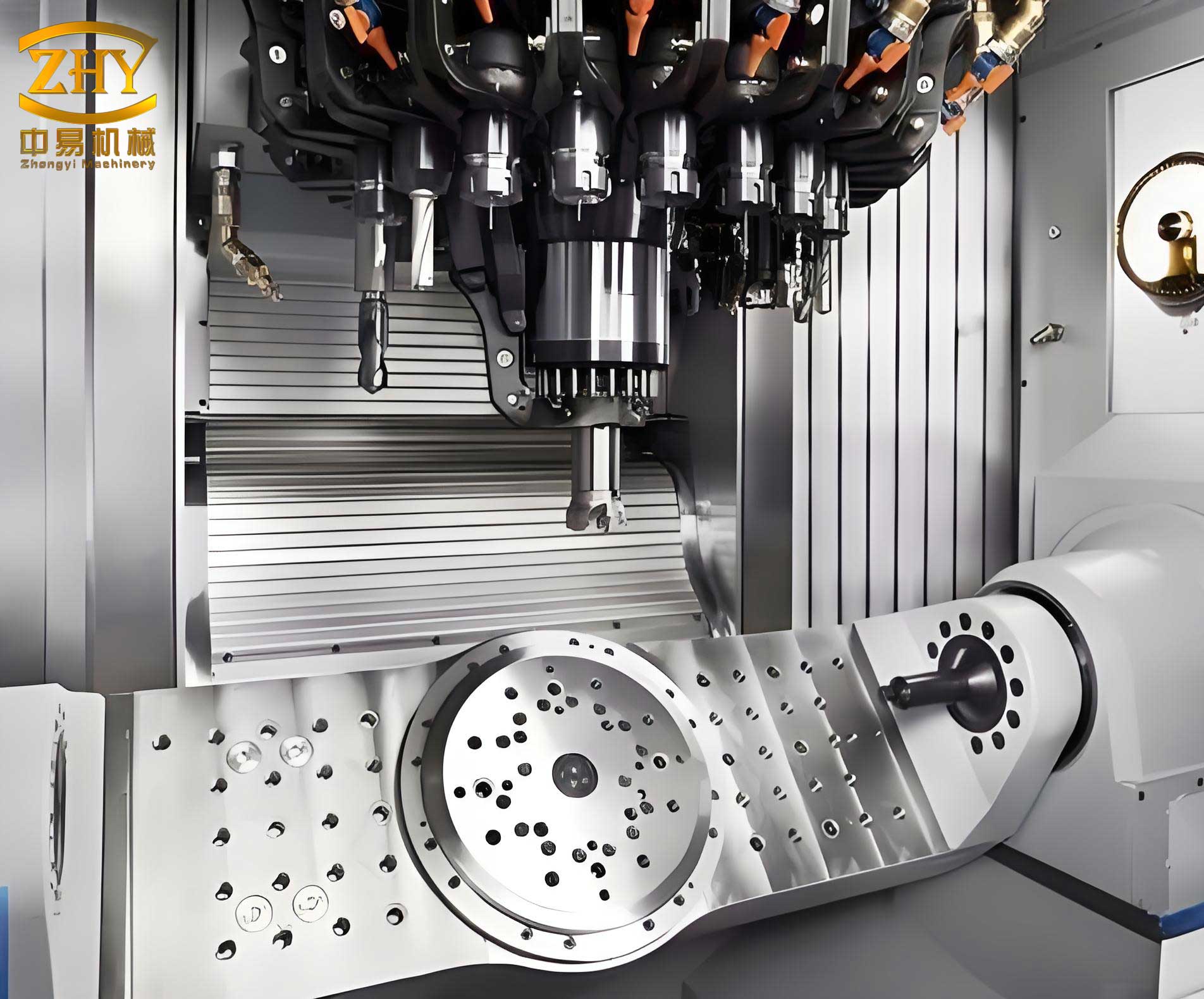
The coarse graphite defect in machine tool castings is a critical concern because it directly impacts the surface finish and mechanical properties after machining. Upon visual inspection, the machined surfaces show gray-black microholes resembling “flyspeck” patterns, filled with graphite powder that contaminates the processing area. Metallographic analysis of these sections reveals coarse graphite flakes, distinguishing it from other defects like shrinkage pores, porosity, slag inclusions, or gas holes. This defect typically occurs in the upper surfaces of thick castings due to slow cooling rates, which allow graphite to grow excessively. Understanding this is essential for implementing targeted solutions in machine tool casting production.
To systematically address coarse graphite in machine tool castings, we first analyzed the causes across multiple aspects, including structural design, casting process, and melting operations. Below is a summary table categorizing the primary causes:
| Category | Specific Causes | Impact on Graphite Formation |
|---|---|---|
| Structural Design | Large wall thickness differences (e.g., worktables 3–4 times thicker than other sections) | Slower cooling in thick areas prolongs solidification, promoting graphite growth. |
| Casting Process Design | Improper gating and risering, concentrated ingates, excessive machining allowances on thick surfaces | Creates thermal hot spots, reducing cooling rates and encouraging coarse graphite. |
| Melting Process | Use of high-grade pig iron and high-carbon scrap steel | Increases carbon equivalent (CE), raising graphite precipitation tendency. |
| Inconsistent melting parameters: low coke-to-iron ratio, high base coke height | Leads to excessive carbon pickup and low melting temperatures. | |
| Inadequate chemical composition control: high carbon and silicon levels | Elevates CE, favoring coarse graphite formation in machine tool castings. |
From this analysis, we derived that the fundamental mechanism involves slow cooling rates in thick sections, combined with high carbon equivalent in the iron. The carbon equivalent (CE) is a key parameter in cast iron, calculated using the formula: $$CE = \%C + 0.33(\%Si + \%P)$$ where %C is carbon content, %Si is silicon, and %P is phosphorus. For machine tool castings, a high CE (typically above 4.2%) increases the risk of coarse graphite, especially in slow-cooling regions. Additionally, the solidification time \( t_s \) can be approximated by Chvorinov’s rule: $$ t_s = k \cdot V/A^2 $$ where \( V \) is volume, \( A \) is surface area, and \( k \) is a mold constant. Thicker sections have a higher \( V/A \) ratio, leading to longer \( t_s \) and coarser graphite.
To mitigate these issues, we implemented a multi-faceted strategy focusing on design, process, and melting improvements. The following table outlines the core solutions we adopted for machine tool castings:
| Solution Area | Specific Measures | Technical Rationale |
|---|---|---|
| Structural Design Modifications | Redesign to minimize wall thickness differences; thin down thick sections like worktables. | Enhances uniform cooling, reduces thermal hot spots in machine tool castings. |
| Casting Process Optimizations | Use dispersed gating systems and risers; apply chill plates (metal or graphite) in thick areas. | Accelerates cooling, prevents graphite coarsening in critical zones of machine tool castings. |
| Adopt step-gating techniques and control machining allowances on guideways. | Balances solidification, avoids excessive material removal that exposes defects. | |
| Avoid graphite chills for surfaces requiring induction hardening to prevent cracking. | Ensures metallurgical integrity in high-stress areas of machine tool castings. | |
| Melting Process Enhancements | Select low-carbon scrap steel and low-grade pig iron (e.g., Z18, Z22); mix pig irons from different sources. | Reduces carbon equivalent and minimizes genetic effects from raw materials. |
| Control chemical composition: target C 3.2–3.6%, Si 1.8–2.2%, Mn 0.8–1.2%, P < 0.1%, S < 0.1%. | Lowers CE for thick machine tool castings; adjust based on wall thickness. | |
| Employ effective inoculation: use Sr/Ba-containing inoculants for long-lasting effects; combine with rare-earth silicide. | Refines graphite structure, counters inoculation fade in machine tool castings. | |
| Maintain melting temperature above 1450°C; scrap steel addition ≥30%. | Promotes finer graphite nucleation and reduces carbon pickup. | |
| Pouring Practice Adjustments | Set detailed pouring temperature ranges (e.g., 1350–1400°C); slow pour at end; use hot metal for topping. | Controls cooling rates and minimizes thermal gradients in machine tool castings. |
In the melting process, precise control of chemical composition is paramount for preventing coarse graphite in machine tool castings. We established optimal ranges based on casting thickness, as shown in the formula below for adjusting carbon equivalent: $$ CE_{adjusted} = \%C + 0.33\%Si – k_t \cdot (T_{pour} – T_{base}) $$ where \( k_t \) is a temperature coefficient (typically 0.001–0.002 per °C), \( T_{pour} \) is pouring temperature, and \( T_{base} \) is a reference temperature (e.g., 1400°C). For thick-section machine tool castings, we aim for a lower CE, often below 4.0%, by reducing carbon and silicon contents. Additionally, we use anti-graphitizing elements like manganese and boron, with their effects quantified by: $$ GSI = \frac{CE}{1 + 0.1(\%Mn + \%Cr)} $$ where GSI is the Graphite Saturation Index, and higher values indicate greater risk of coarse graphite. By targeting a GSI < 3.8 for machine tool castings, we achieve finer graphite structures.
The inoculation process plays a critical role in graphite refinement. We transitioned from conventional FeSi inoculants to长效孕育剂 (long-effect inoculants) containing strontium and barium, which provide sustained nucleation sites. The inoculation efficiency \( \eta \) can be expressed as: $$ \eta = \frac{N_g}{N_0} \cdot e^{-t/\tau} $$ where \( N_g \) is graphite nodule count, \( N_0 \) is initial nucleus density, \( t \) is time after inoculation, and \( \tau \) is the fade time constant. For machine tool castings, we select inoculants with \( \tau > 15 \) minutes to ensure effectiveness throughout pouring. The recommended addition rate is 0.1–0.2% of the melt weight, half that of FeSi, reducing the risk of over-inoculation that can increase eutectic cell count and promote coarse graphite.
Regarding casting process design, we adopted均衡凝固工艺 (balanced solidification principles) to optimize cooling rates. The gating system is designed to ensure uniform heat distribution, with ingates positioned away from thick sections like guideways. We use computational simulations to predict temperature gradients, employing the Fourier heat equation: $$ \frac{\partial T}{\partial t} = \alpha \nabla^2 T $$ where \( T \) is temperature, \( t \) is time, and \( \alpha \) is thermal diffusivity. By applying chills in isolated hot spots, we enhance heat extraction, reducing the local solidification time \( t_s \) by up to 30% in machine tool castings. For example, chromium ore sand in core molds can further accelerate cooling, with its effectiveness modeled by: $$ Q_{chill} = h_c \cdot A_c \cdot (T_{cast} – T_{mold}) $$ where \( Q_{chill} \) is heat flux, \( h_c \) is heat transfer coefficient, \( A_c \) is chill area, and \( T_{cast} \) and \( T_{mold} \) are temperatures of casting and mold, respectively.
To illustrate the chemical composition adjustments, here is a detailed table for different wall thicknesses of machine tool castings:
| Wall Thickness (mm) | Carbon (%) | Silicon (%) | Manganese (%) | Phosphorus (max %) | Sulfur (max %) | Target Carbon Equivalent (CE) |
|---|---|---|---|---|---|---|
| 20–50 | 3.4–3.6 | 1.9–2.2 | 0.9–1.1 | 0.08 | 0.10 | 4.1–4.3 |
| 50–100 | 3.2–3.5 | 1.8–2.0 | 1.0–1.2 | 0.08 | 0.10 | 3.9–4.1 |
| >100 (thick sections) | 3.0–3.3 | 1.6–1.9 | 1.1–1.3 | 0.07 | 0.09 | 3.7–3.9 |
In practice, we also monitor the melting process through pre-pour tests. The三角试片 (triangular test piece) method is used to assess white iron tendency, which correlates with graphite fineness. The白口宽度 (white width) \( W_w \) should be controlled within 2–5 mm for machine tool castings, calculated as: $$ W_w = k_w \cdot (CE – CE_{crit}) $$ where \( k_w \) is an empirical constant (approx. 10 mm per %CE), and \( CE_{crit} \) is the critical carbon equivalent for chill formation (around 3.8%). If \( W_w \) is too small, indicating high CE, we add alloying elements like chromium or antimony to refine graphite. For instance, chromium addition follows the stoichiometric relation: $$ \%Cr_{added} = 0.1 \cdot (CE_{actual} – CE_{target}) $$ which typically ranges 0.1–0.3% for machine tool castings with coarse graphite risks.
Furthermore, the pouring phase is critical for controlling defects in machine tool castings. We established standard operating procedures (SOPs) for each casting type, specifying pouring temperatures and times. The pouring time \( t_p \) is determined by: $$ t_p = \frac{W}{\rho \cdot A_g \cdot v} $$ where \( W \) is casting weight, \( \rho \) is iron density (≈7.2 g/cm³), \( A_g \) is total ingate area, and \( v \) is flow velocity (typically 0.5–1.0 m/s). For large machine tool castings, \( t_p \) is kept under 60 seconds to avoid temperature drop and ensure rapid mold filling. Post-pour, we perform补浇 (topping) with high-temperature iron to compensate for shrinkage and reduce graphite flotation. This is especially important for thick worktables, where the temperature gradient \( \Delta T \) across the section should be minimized: $$ \Delta T = T_{pour} – T_{solidus} \cdot \frac{x}{L} $$ where \( x \) is distance from surface, \( L \) is section thickness, and \( T_{solidus} \) is solidus temperature (≈1150°C). By maintaining \( \Delta T < 100°C \) through controlled pouring, we inhibit coarse graphite formation.
The implementation of these measures has yielded significant improvements in our production of machine tool castings. We now produce over 600 tons of machine tool castings monthly, with defect rates for coarse graphite reduced by more than 90%. Quality verification through machining and customer feedback, including exports to international markets, confirms that thick worktable and guideway surfaces meet stringent requirements. Key performance metrics are summarized below:
| Metric | Before Improvements | After Improvements | Improvement (%) |
|---|---|---|---|
| Coarse Graphite Defect Rate | 15–20% of thick castings | <2% of thick castings | >90% reduction |
| Carbon Equivalent Control | CE 4.3–4.5 (uncontrolled) | CE 3.8–4.0 (tight control) | ~10% decrease |
| Machining Surface Quality | Rough, graphite-filled pores | Smooth, defect-free surfaces | Near 100% acceptance |
| Production Consistency | High variability | Stable across batches | Measured by σ reduction of 50% |
In conclusion, preventing coarse graphite in machine tool castings requires a holistic approach integrating design, process, and metallurgical controls. From our experience, the熔炼方面 (melting aspects) are particularly crucial when casting geometry is fixed. By adhering to strict工艺规程 (process specifications)—such as optimizing carbon equivalent via $$ CE = \%C + 0.33\%Si $$, employing effective inoculation, and using chills strategically—we have successfully mitigated this defect. The key takeaway is that proactive monitoring and adaptive measures, tailored to the unique demands of machine tool castings, can ensure high-quality outcomes. As foundry practices evolve, continuous refinement of these parameters will further enhance the reliability and performance of machine tool castings in industrial applications.