
The production of high-integrity, complex-shaped components like impellers represents a significant challenge and a pinnacle of achievement in the realm of sand casting products. Among these, aluminum alloy impellers are particularly demanding due to their stringent requirements for structural soundness, metallurgical quality, and dimensional accuracy to withstand high rotational speeds and operational stresses. This article details a comprehensive methodology, from initial concept to validated process, for manufacturing a large ZL114A aluminum alloy impeller using resin sand casting. The focus is on synthesizing fundamental casting principles with modern simulation tools to achieve an optimal design that balances quality, cost, and manufacturability—a core objective in advancing sand casting products.
1. Fundamental Principles of Sand Casting for Complex Geometries
The successful creation of premium sand casting products hinges on mastering the interplay between material properties, geometry, and process physics. For aluminum alloys like ZL114A, key considerations include:
- Solidification Characteristics: Aluminum alloys have a significant solidification shrinkage, which must be managed through controlled thermal gradients and effective feeding to prevent shrinkage porosity. The volumetric shrinkage $\beta$ can be approximated for many Al-Si alloys as:
$$\beta \approx 3-6\%$$ - Fluid Dynamics: The flow of molten metal must be tranquil to avoid turbulence, which leads to oxide film entrainment (bifilm defects), a critical detriment to the mechanical properties of sand casting products. The Reynolds number $Re$ is a key indicator:
$$Re = \frac{\rho v D_h}{\mu}$$
where $\rho$ is density, $v$ is velocity, $D_h$ is the hydraulic diameter, and $\mu$ is dynamic viscosity. Maintaining flow in the laminar or low turbulent regime ($Re < 2000$) is often targeted for critical sections. - Heat Transfer: The rate of heat extraction by the sand mold dictates the solidification sequence. Fourier’s law governs this:
$$q = -k \frac{dT}{dx}$$
where $q$ is heat flux, $k$ is thermal conductivity of the mold, and $dT/dx$ is the temperature gradient. Designing the mold and cooling aids to promote directional solidification towards the feeder is paramount.
2. Systematic Casting Process Design Methodology
The design process for high-performance sand casting products follows a logical sequence of decisions, each building upon the previous to mitigate specific defect risks.
2.1 Analysis of Casting Geometry and Requirements
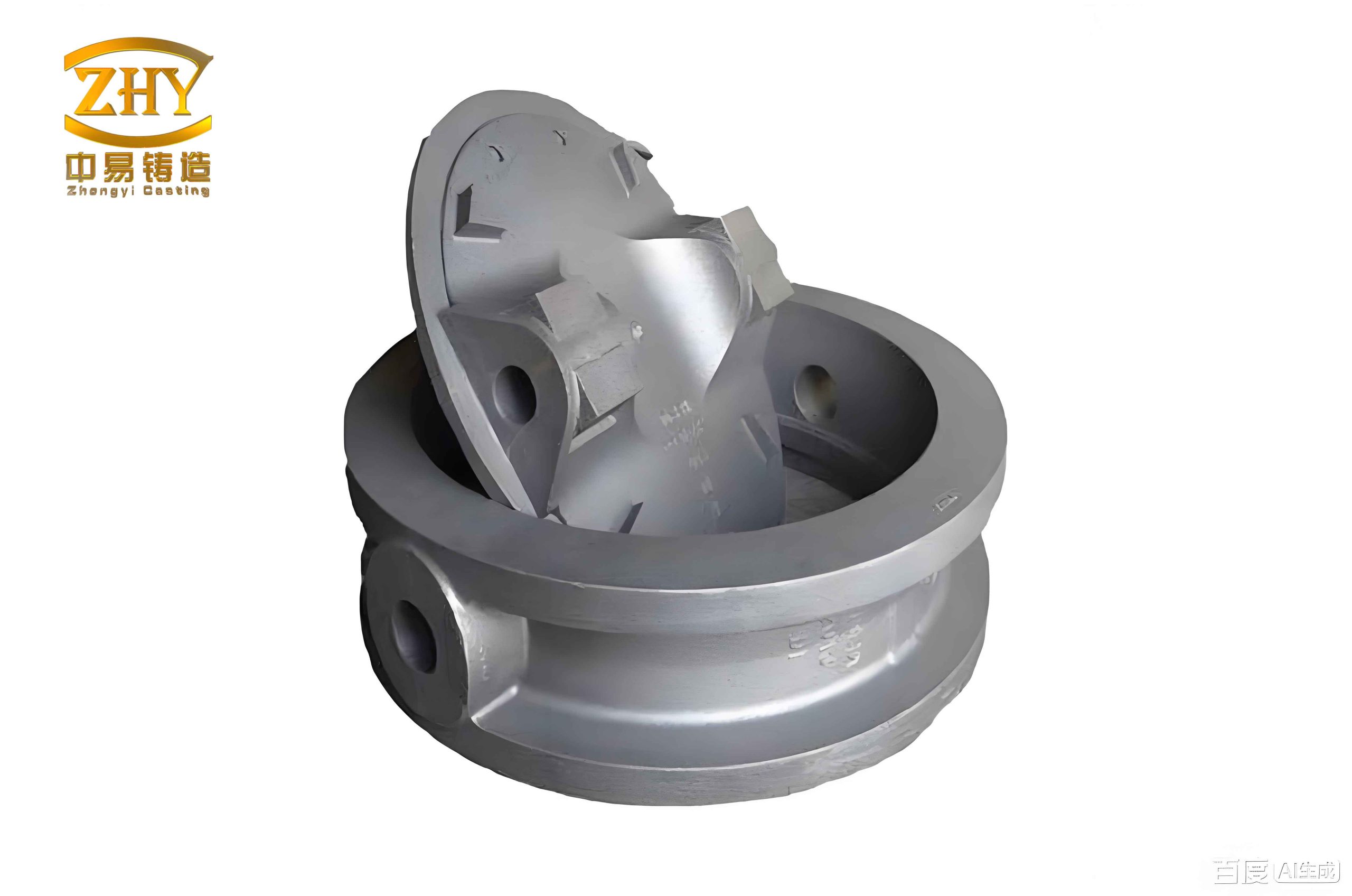
The subject impeller is a rotationally symmetric disc with a major diameter of 936 mm and a height of 210 mm. It features 16 thin-walled blades (6 mm minimum thickness) radiating from a central hub with thick sections up to 100 mm. The key functional surfaces are the planar faces of the central spool (web). The material specification (ZL114A), coupled with non-destructive testing requirements (X-ray, dye-penetrant) and a high service speed of 2950 rpm, mandates an exceptional level of internal soundness and mechanical integrity. This defines the primary goal for these high-value sand casting products.
2.2 Critical Decision 1: Pouring Position
The orientation of the casting in the mold is the first and most critical decision. Two primary options were evaluated against the governing principles for quality sand casting products:
| Pouring Position | Advantages | Disadvantages/Risks | Suitability for Impeller |
|---|---|---|---|
| Web Plane Upward | Simpler core support and placement. | Critical web surface is last to fill and solidify, prone to shrinkage porosity, gas entrapment, and non-metallic inclusions. | Poor. Fails to meet primary quality requirement. |
| Web Plane Downward | Critical web surface is filled first by clean metal and solidifies under hydrostatic pressure, promoting dense, sound microstructure. Gas and inclusions float away from critical zone. | Requires robust core spanning the cavity. Slightly more complex mold assembly. | Optimal. Prioritizes casting quality. Resin sand core strength is sufficient. |
The decisive factor was prioritizing metallurgical quality in the critical stress-bearing region. Therefore, the web-plane-down orientation was selected, ensuring the most favorable thermal and physical conditions for the important sections of these sand casting products.
2.3 Critical Decision 2: Gating and Feeding System Architecture
The design of the metal delivery system is paramount for achieving sound sand casting products. For the symmetric impeller, several gating concepts were simulated. The optimal system unifies the benefits of bottom and center pouring through an integrated sprue/feeder design.
System Components and Rationale:
- Central Downtapered Sprue/Feeder: Positioned in the central hub bore. This provides a short, direct flow path, minimizing heat loss and filling time. It also acts as a massive thermal reservoir, functioning as a primary feeder (riser) during solidification.
- Bottom Distributor Cone: Placed in the drag (bottom mold) directly below the sprue exit. Its function is expressed by redirecting the metal stream’s momentum:
$$\vec{p}_{in} = m\vec{v}_{in} \rightarrow \vec{p}_{out} = m\vec{v}_{out, radial}$$
The cone geometry transforms the vertical downward flow into a more radial, upward flow along the blade roots, ensuring uniform, gentle filling from the bottom-up. - Dual Filtration System:
- A ceramic foam filter in a recess within the upper part of the sprue.
- A refractory fiber mesh at the parting line between the top mold and the core.
This dual-stage filtration significantly enhances slag and oxide film capture efficiency, crucial for clean metal in high-performance sand casting products. The filters also dampen turbulent flow, promoting laminar filling.
The mathematical basis for the system’s efficacy lies in combining the Chvorinov rule for solidification time with Bernoulli’s principle for fluid flow. The central feeder solidifies last due to its high modulus $M$ (Volume/Surface Area), ensuring it feeds the casting:
$$t_s = k \left( \frac{V}{A} \right)^n = k M^n$$
where $t_s$ is solidification time, and $k$ and $n$ are constants. Concurrently, the system minimizes dynamic pressure and velocity at the ingate through the flow-resistive filters and the distributor, reducing $Re$ and turbulence.
2.4 Critical Decision 3: Supplemental Feeding (Risers) and Mold Design
Initial simulation of the gating system alone indicated potential thermal centers (hot spots) at the junctions between the outer blade tips and the curved transition surfaces of the hub. To eliminate associated shrinkage risks, supplemental feeding was required. The choice was between chills and risers.
While chills could locally increase cooling rate, their placement on the complex curved surfaces was impractical for molding. Therefore, six tapered open-top risers were strategically positioned on the upper hub periphery above the identified hot spots. Their volume was designed using the feeding distance concepts and modulus extension principles to ensure they remain liquid longer than the regions they feed.
The mold was designed as a no-flask assembly using cold-setting resin sand for both cores and molds, ensuring high strength and precision. The single, large core forms the internal cavity and blade passages. The drag incorporates the distributor cone and alignment features, while the cope includes the riser openings and lightening holes. This design minimizes the number of mold parts, simplifies assembly, and reduces material use, contributing to the cost-effectiveness of the sand casting products.
3. Numerical Simulation as a Validation and Optimization Tool
Modern simulation software (exemplified by tools like AnyCasting) is indispensable for virtual prototyping of sand casting products. It solves the governing equations of fluid flow, heat transfer, and solidification to predict potential defects before tooling is made.
3.1 Governing Equations for Casting Simulation
The simulation is based on solving coupled partial differential equations:
a) Fluid Flow (Navier-Stokes with Free Surface):
$$\frac{\partial \vec{v}}{\partial t} + (\vec{v} \cdot \nabla) \vec{v} = -\frac{1}{\rho} \nabla p + \nu \nabla^2 \vec{v} + \vec{g}$$
$$\nabla \cdot \vec{v} = 0$$
where $\vec{v}$ is velocity, $p$ is pressure, $\nu$ is kinematic viscosity, and $\vec{g}$ is gravity.
b) Heat Transfer and Solidification:
$$\rho c_p \frac{\partial T}{\partial t} + \rho c_p (\vec{v} \cdot \nabla T) = \nabla \cdot (k \nabla T) + \rho L \frac{\partial f_s}{\partial t}$$
where $c_p$ is specific heat, $T$ is temperature, $k$ is thermal conductivity, $L$ is latent heat, and $f_s$ is solid fraction.
c) Defect Prediction Criteria: Shrinkage porosity is often predicted using the Niyama criterion $Ny$:
$$Ny = \frac{G}{\sqrt{\dot{T}}}$$
where $G$ is the temperature gradient and $\dot{T}$ is the cooling rate. Regions with $Ny$ below a critical threshold (e.g., ~1 °C1/2·s1/2/mm for Al alloys) are prone to microporosity.
3.2 Simulation Results and Iterative Optimization
The initial design with gating and risers was simulated. Key results are summarized below:
| Simulation Phase | Key Observations | Design Implication |
|---|---|---|
| Filling (18.74 s total) | Sequential, bottom-up filling. Metal flows radially from distributor, uniformly ascends blade channels. No visible turbulence or air entrapment. Filters effective in calming flow. | Confirms gating system design. Optimal fill pattern for defect minimization in sand casting products. |
| Solidification | Directional progression from thin blades and outer regions towards the central hub and risers. The central sprue/feeder and the six peripheral risers are the final regions to solidify, creating a controlled thermal gradient. | Validates the feeding strategy. The designed thermal centers are now inside the feeders. |
| Defect Prediction (Porosity) | Predicted shrinkage defects are isolated almost entirely within the central feeder and the six risers. The casting itself, including the previously identified hot spots, is predicted to be sound. | Confirms the riser design effectively moved the shrinkage from the casting into the feeders. Minor riser size adjustments were made iteratively. |
The final process parameters derived from simulation are critical for producing consistent sand casting products:
- Optimal Pouring Temperature: ~720-740°C (for ZL114A).
- Controlled Fill Time: ~18-20 seconds.
- Riser Dimensions: Diameter ~100 mm, height ~190 mm, with a 10° taper for easy removal.
4. Synthesis and Best Practices for Impeller Sand Casting
The successful process design for the aluminum alloy impeller demonstrates a holistic approach applicable to a wide range of complex sand casting products. The following integrated principles emerged:
| Design Principle | Technical Implementation | Benefit for Sand Casting Products |
|---|---|---|
| Quality-First Orientation | Place critical functional surfaces downward to benefit from early filling and favorable solidification pressure. | Maximizes metallurgical soundness and mechanical properties in critical zones. |
| Unified Gating/Feeding | Combine sprue and primary feeder in a central location for symmetric parts. Use flow modifiers (cones, filters) to control fluid dynamics. | Simplifies molding, reduces heat loss, ensures directional solidification, and improves yield. |
| Proactive Defect Mitigation | Use simulation to identify thermal centers and strategically place risers of calculated modulus. Employ multi-stage filtration. | Moves shrinkage defects into removable feeders and minimizes oxide inclusions. |
| Manufacturability & Cost | Use high-strength resin sand for precision. Minimize number of cores and mold parts. Design for easy riser removal (machining). | Reduces pattern cost, improves dimensional accuracy, simplifies foundry operations, and is suitable for low-volume production. |
The synergy between a fundamentally sound design—prioritizing thermal and fluid dynamics principles—and validation through advanced numerical simulation is the cornerstone for producing reliable, high-performance sand casting products like aluminum alloy impellers. This methodology ensures that the final cast component meets its demanding service requirements while maintaining economic viability in production.