
The continuous advancement of science and technology has propelled the foundry industry towards more efficient, precise, and environmentally sustainable processes. Among these, lost foam casting (LFC) stands out as a transformative technology, garnering widespread attention for its low cost, high dimensional accuracy, clean production, design flexibility, and exceptional suitability for complex castings. It aligns perfectly with the overarching trend of foundry development in the new century and holds vast market potential. Initially applied to simple metal components, lost foam casting has now penetrated demanding sectors like the petroleum machinery industry, driving significant innovation and yielding remarkable results. This article delves into the principles, varieties, technological innovations, and the groundbreaking application of lost foam casting within the petroleum machinery sector.
For professionals familiar with the field, lost foam casting is recognized as one of the most promising green casting technologies of the 21st century. It is a near-net-shape, precision forming process that utilizes unbonded dry sand for molding, eliminating the need for core making and mold assembly, thereby drastically reducing pollution. In essence, the process involves creating a foam pattern—typically from expandable polystyrene (EPS) or similar materials—that is an exact replica of the final metal part. This pattern is coated with a refractory slurry, dried, and then embedded in loose, unbonded sand within a flask. Molten metal is poured directly onto the foam pattern, which vaporizes and is replaced by the metal, resulting in a precise casting that mirrors the pattern’s geometry. This process, evolving from investment and full mold casting, relies on the application of a vacuum to compact the sand and draw away the gaseous by-products of pattern decomposition. The primary advantages include superior surface finish, reduced cleaning and machining, and the environmental benefit of cleaner emissions, making it a widely adopted technology in advanced industrial nations.
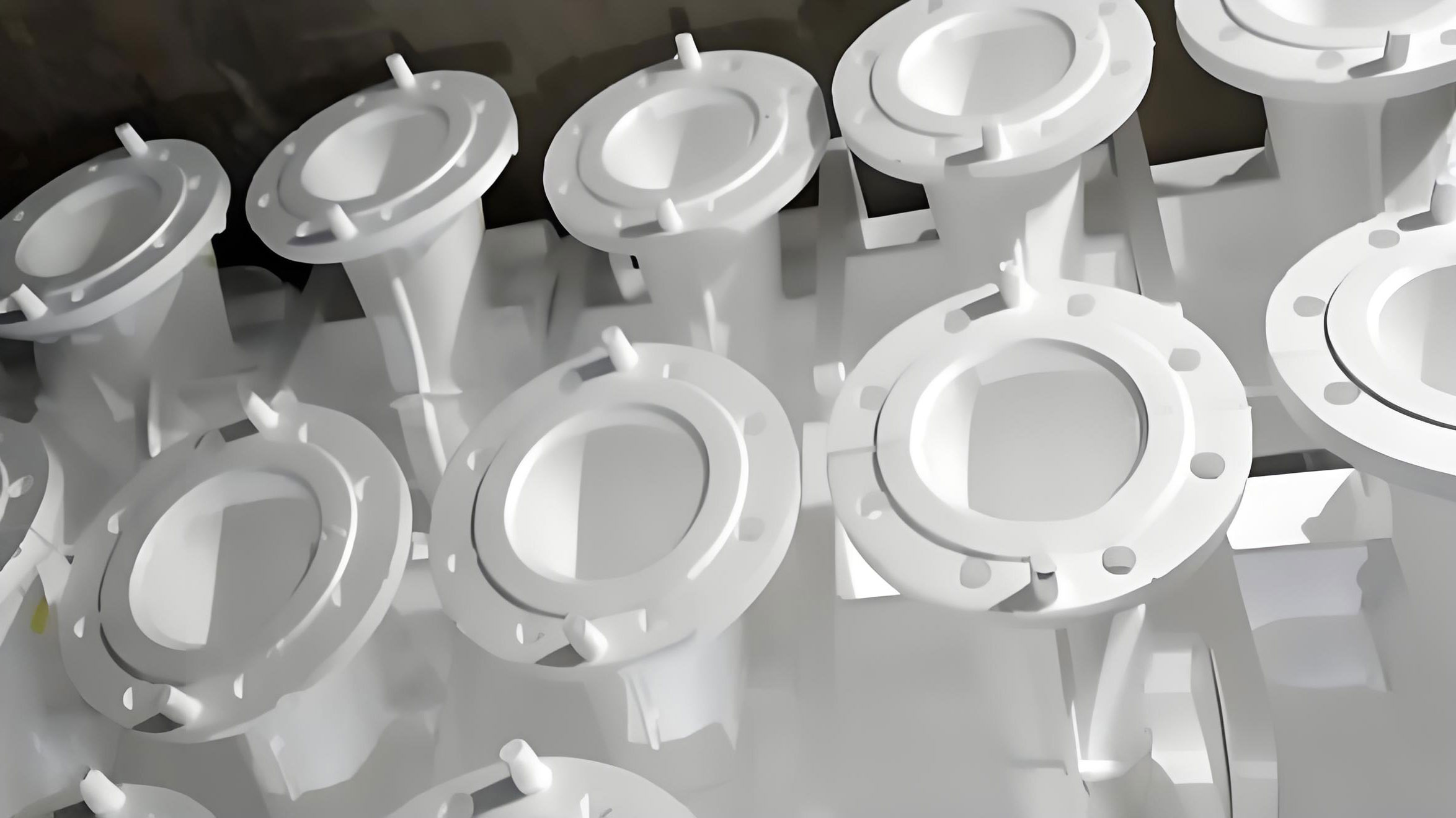
The family of lost foam casting technologies is diverse, with each variant offering unique characteristics suited for specific applications. A summary of key advanced lost foam casting techniques is presented below:
| Technology Variant | Core Principle / Combination | Key Advantages & Characteristics |
|---|---|---|
| Vacuum Low-Pressure Lost Foam Casting | Integrates vacuum-assisted LFC with low-pressure counter-gravity filling. | Lower casting cost and equipment investment than die casting; higher precision, productivity, and mechanical properties than sand casting. Operates at lower pouring temperatures, ideal for various non-ferrous alloys. |
| Lost Foam Shell Casting | Hybrid of investment casting and LFC. A foam pattern is coated to create a thin ceramic shell before casting. | Lower cost than conventional investment casting; capable of producing larger alloy castings with high precision. Excellent pattern assembly flexibility. |
| Vibratory Lost Foam Casting | Applies controlled vibration (frequency & amplitude) to the mold during metal solidification. | Vibration induces relative motion between liquid and solid phases, fragmenting dendrites. Results in refined grain structure and enhanced mechanical properties. A simple, pollution-free method for microstructure control. |
| Pressure Lost Foam Casting | Applies positive pressure during or after pouring to enhance feeding and density. | Reduces shrinkage porosity, improves metal density and mechanical strength, particularly for thick-section castings. |
| Semi-Solid Lost Foam Casting | Combines LFC with semi-solid metal (SSM) processing. | Utilizes thixotropic slurry, reducing turbulence and gas entrapment. Yields castings with extremely low porosity, superior surface finish, and enhanced mechanical properties. |
The establishment of a lost foam casting production line involves meticulous planning of functional modules, installation of core equipment (pattern molding machines, coating stations, sand handling systems, pouring and vacuum control units), and often, the in-house development of auxiliary equipment. The core process flow can be modeled as a sequence of critical states. The pattern density evolution during pre-expansion can be described by an exponential decay model:
$$ \rho(t) = \rho_f + (\rho_i – \rho_f) e^{-kt} $$
where $\rho(t)$ is the bead density at time $t$, $\rho_i$ is the initial bead density, $\rho_f$ is the target final density, and $k$ is a rate constant dependent on steam pressure and temperature. The process chain itself is systematic:
- Pattern Making: Pre-expansion of raw beads → Injection molding into final foam patterns → Pattern assembly into clusters.
- Coating & Drying: Dipping or spraying of refractory coating → Controlled drying to achieve required permeability and strength.
- Molding: Placement of coated cluster in flask → Sequential filling and compaction of dry sand under vibration → Application of vacuum to rigidize the mold.
- Pouring & Solidification: Pouring of molten metal → Pattern vaporization and metal replacement → Continued vacuum application during solidification.
- Shakeout & Cleaning: Removal of casting from sand → Minimal cleaning (no sand cores to remove) → Cut-off and finishing.
The key advantages of this workflow are intrinsic: high dimensional accuracy, near-net-shape capability, design freedom for complex internal geometries, elimination of cores and binders, and reduced capital and operating costs. However, limitations such as pattern integrity, coating control, and the management of pyrolysis gases must be carefully managed to ensure success. The sand filling and compaction dynamics are crucial and can be analyzed in terms of energy transfer. The effectiveness of vibration can be related to the acceleration $a$ applied:
$$ a = A (2\pi f)^2 \sin(2\pi f t) $$
where $A$ is the amplitude and $f$ is the frequency. Optimal compaction is achieved when this acceleration exceeds a threshold that facilitates sand particle rearrangement.
Domestically, the adoption of lost foam casting has seen rapid growth, with the number of enterprises utilizing the technology expanding from a handful to several hundred. This growth, however, has been accompanied by challenges, as some ventures discontinued operations due to unmet expectations. Successful implementations also abound. The key to sustainable development lies in analyzing both failures and successes, distilling lessons learned to enhance the overall understanding and mastery of the lost foam casting process. A comprehensive optimization strategy is required, encompassing raw materials (pattern beads), coating technology, dry sand compaction techniques, and the core lost foam casting process parameters. This holistic approach is essential for unlocking its full potential and securing a brighter future for the technology.
| Process Parameter | Optimization Focus | Impact on Casting Quality |
|---|---|---|
| Pattern Density & Bead Fusion | Control of pre-expansion temperature/time, steam pressure. | Determines gas evolution volume, affecting surface finish (fold defects) and porosity. |
| Coating Permeability & Thickness | Formulation of refractory slurry, viscosity control, drying cycle. | Critical for allowing gas escape, preventing metal penetration, and ensuring mold strength. |
| Pouring Temperature & Rate | Alloy-specific optimization, synchronized with vacuum level. | Balances complete pattern degradation and replacement with minimization of thermal shock and turbulence. |
| Vacuum Level & Timing | Dynamic control: initial high vacuum for mold rigidity, modulated during pouring. | Ensures mold stability, aids in drawing gases away from the metal front, and controls fill profile. |
Innovation is the lifeblood for the continued evolution of lost foam casting. Stagnation leads to obsolescence. A primary area for innovation is the pattern molding process itself. The adoption of advanced feeding methods, such as retractable long-nozzle injection, allows for precise control over complex pattern geometries by managing the relationship between injection pressure and nozzle diameter. For challenging, deep, or thin-walled sections prone to incomplete filling or distortion, the design of specialized nozzle heads or venting strategies ensures the foam completely fills the mold cavity, resulting in a dimensionally accurate pattern. The governing equation for flow during injection can be approximated using a modified Bernoulli’s principle, accounting for viscous losses:
$$ P_{in} + \frac{1}{2}\rho v_{in}^2 = P_{out} + \frac{1}{2}\rho v_{out}^2 + \Delta P_{friction} + \Delta P_{form} $$
where $P$ is pressure, $\rho$ is the foam melt density, $v$ is velocity, and the $\Delta P$ terms account for losses due to friction and form (geometry changes).
Secondly, the formulation of coatings demands continuous R&D. Developing foundational coating recipes that are both highly practical and approach the performance benchmarks of international leaders is crucial. This not only saves significant capital but also fosters indigenous intellectual property and self-reliance. The coating’s gas permeability is a critical design parameter, often engineered to be optimal within the temperature range of pattern decomposition. Finally, process methodology must be refined. A “one-size-fits-all” approach is ineffective. The gating and feeding system design must be tailored to the specific casting geometry. A methodology favoring top pouring as the primary method, supplemented by stepped or multiple gates, can be employed to regulate the flow field, thereby achieving a rational thermal gradient and directional solidification—truly “prescribing the right remedy for the illness.” The heat transfer during filling and solidification is governed by the energy balance involving the metal’s enthalpy and the heat required for pattern degradation:
$$ \rho_m C_{p,m} V_m \frac{dT_m}{dt} + \rho_m L_f \frac{df_s}{dt} = -h A (T_m – T_s) – \dot{Q}_{vaporization} $$
where $\rho_m$ is metal density, $C_{p,m}$ is specific heat, $V_m$ is volume, $L_f$ is latent heat, $f_s$ is solid fraction, $h$ is heat transfer coefficient, $A$ is interfacial area, $T$ is temperature, and $\dot{Q}_{vaporization}$ is the heat sink from foam pyrolysis.
The innovations in lost foam casting have enabled its successful application across various heavy-industry sectors, most notably in petroleum machinery. This industry demands components that are robust, reliable, and often geometrically complex. The technology has been successfully deployed to manufacture high-quality, large-to-medium-sized castings such as pumping unit components (beam, saddle, gearbox housings), mud pump bodies and liners, and parts for wheel-mounted well servicing units. The technical specifications of these castings consistently meet or exceed stringent requirements. This technological leap has delivered substantial economic benefits and outstanding application outcomes for the petroleum machinery sector.
The benefits are quantifiable and multifaceted. The surface quality of the new generation of castings is significantly improved—smoother, free from flash and burrs, with excellent replication of pattern details. Dimensional stability is enhanced, with minimal tolerances, leading to a marked reduction in metal waste from over-engineering. This inherent quality improvement translates directly into higher market value; castings produced via advanced lost foam casting command a premium, often 20% to 30% higher than equivalent sand-cast parts. Furthermore, the environmental profile is superior. Modern lost foam casting lines integrate advanced dust collection and exhaust gas treatment systems. This drastically reduces the emission of solid particulates and gaseous pollutants. The purification rate for foam pyrolysis by-products is continuously improving, achieving compliant emissions standards. This significantly alleviates foundry shop pollution, creating a win-win scenario that marries economic efficiency with environmental stewardship and operational effectiveness.
| Component | Typical Alloy | Key Benefits Realized | Economic/Performance Impact |
|---|---|---|---|
| Pumping Unit Gearbox Housing | Ductile Iron (e.g., QT450-10) | Near-net-shape complex internal passages, excellent surface finish, reduced machining. | 30% reduction in machining time, 15% increase in fatigue life due to better surface integrity. |
| Mud Pump Fluid End Body | High-Alloy Steel or Ductile Iron | Precision of internal valves and ports, high dimensional consistency, good pressure integrity. | Elimination of core-related defects, extended service life, reduced downtime. |
| Valve Bodies & Manifolds | Carbon Steel or Stainless Steel | Integration of multiple internal features into a single casting, no core joints. | Reduced assembly/welding costs, improved flow characteristics, leak-proof design. |
In conclusion, lost foam casting stands as a pivotal modern foundry process whose potential is only beginning to be fully tapped. Its journey from a technology for simple parts to a cornerstone for manufacturing critical components in the petroleum industry underscores its versatility and capacity for innovation. The continuous refinement of its subsidiary technologies—vacuum low-pressure, shell, vibratory methods—provides a toolkit for solving diverse manufacturing challenges. The successful application in petroleum machinery, yielding components with superior quality, economic value, and a greener footprint, serves as a powerful testament to its maturity and future direction. For the industry to maintain and expand its competitive edge in global markets, a sustained commitment to advancing lost foam casting technology, through relentless R&D, process optimization, and creative application, is not just beneficial—it is imperative.