
A flywheel is a fully machined, dynamically balanced rotating part. Every square millimetre of its surface is cut, the blank must be free of surface and internal defects, and any residual distortion shows up directly as imbalance or as an uneven machining allowance. Casting such a part in lost foam (expendable pattern casting) removes the draft angles and the parting line of a conventional sand mould, but it transfers the burden of quality to the pattern, the coating and the filling behaviour of the metal. The work described here concerns a Ø274 × 32 mm HT250 flywheel blank weighing 8.3 kg, produced with a one-piece EPS pattern, an open gating system of 16 parts per cluster, and vacuum-assisted pouring.
What the flywheel demands of the process
The part specification leaves little room for compromise. The section varies from 32 mm at the rim to 14 mm in the web, so the same casting contains a hot, slowly cooling mass and a thin, rapidly cooling plate. The material is a low-alloy HT250 grey iron that must reach 250 MPa tensile strength, be stress-relieved after casting, and hold a narrow hardness window measured 1.5 mm below the machined surface, with a limited spread across the part. The graphite structure is specified as well, since it controls machinability, damping and thermal behaviour.
| Parameter | Specification |
|---|---|
| Envelope / thickness | Ø274 mm × 32 mm |
| Maximum / minimum wall | 32 mm / 14 mm |
| Blank mass | 8.3 kg |
| Material | HT250 low-alloy grey iron, tensile strength ≥ 250 MPa |
| Graphite length grade | 4–7 |
| Graphite form | A + B, with A ≥ 70%; type C not permitted |
| Ferrite content | < 10% |
| Hardness (≥ 1.5 mm below machined surface) | 187–241 HBW |
| Hardness spread within a casting | ≤ 25 HBW |
| Post-cast condition | Stress relieved; all surfaces machined; dynamic balance tested |
The process chain and why defects appear late
Lost foam casting replaces the mould cavity with a polymer pattern that is buried in unbonded dry sand, compacted by vibration, and then displaced by liquid metal. The pattern does not melt and flow away; it decomposes in contact with the incoming metal, and the decomposition products must be drawn through the refractory coating into the sand by the applied vacuum. The casting is therefore the end product of a long serial chain: bead pre-expansion, maturation, pattern moulding, ageing, drying, trimming, gluing into a cluster, coating, drying again, sand filling, compaction, pouring and shakeout.
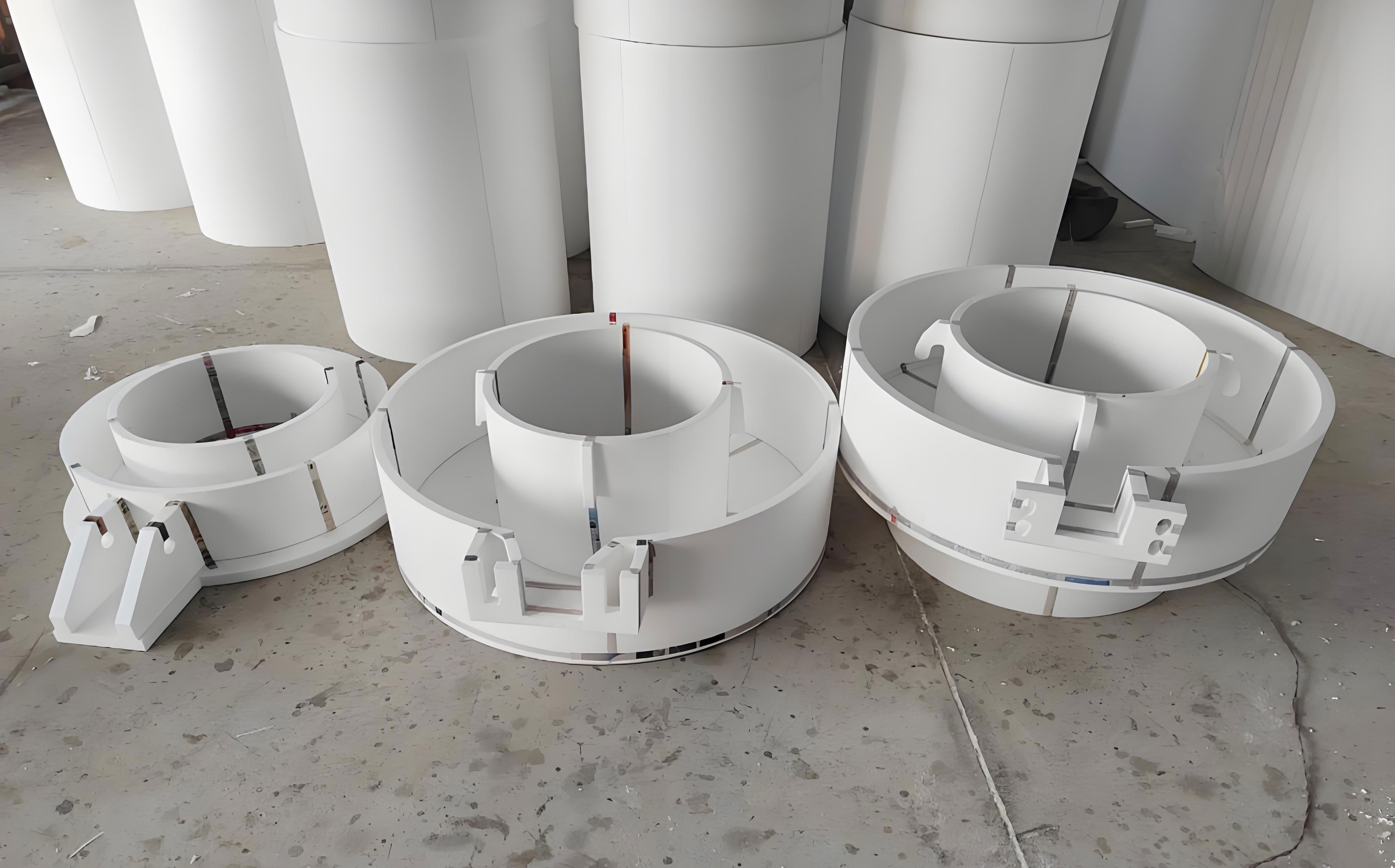
Because the chain is serial, each step contributes only a small deviation, and none of them produces a visible defect on its own. A pattern moulded at slightly low density, a glue line that is too thick, a coating that is 0.2 mm thin at one point, sand that is under-compacted in a corner — the consequences only appear as distortion, slag or penetration after the metal has solidified. Effective control therefore means treating each parameter as a tolerance rather than as a target, and correcting the process at the step where the deviation originates instead of at the finishing bench.
Pattern density is the master variable
The density of the foam sets almost everything downstream: pattern strength and dimensional stability during handling and compaction, the amount of gas that must be evacuated during pouring, the tendency towards carbon pickup, and the surface finish transferred to the casting. For this flywheel the moulded pattern density was held at 20–22 g/L. Since pattern density rises slightly during moulding and ageing from the pre-expanded bead state, the bead itself was pre-expanded to a bulk density of 18–20 g/L, roughly 2 g/L below the finished pattern target. The pre-expanded beads were matured for 4–8 h in a silo before moulding, which allows the blowing agent to diffuse out of the cells and the cell walls to stabilise; moulding too soon gives patterns that shrink and distort after the fact.
One-piece moulding of the flywheel on a hydraulic semi-automatic machine avoided the glued sub-assemblies that would otherwise introduce asymmetric shrinkage. The moulded patterns were then aged in air at room temperature for 10–15 days so that residual moisture and blowing agent could escape, and dried at 40 ± 5 °C and below 30% relative humidity until fully dry. Together, the pattern envelope of roughly 1.5 L and the specified density imply a polymer mass of the order of 30 g per part — the entire gas load that the coating and the vacuum system must handle during filling.
| Stage | Controlled condition |
|---|---|
| Pre-expanded bead bulk density | 18–20 g/L |
| Moulded pattern density | 20–22 g/L |
| Bead maturation | 4–8 h |
| Pattern moulding | Hydraulic semi-automatic machine, single-piece tooling |
| Ambient ageing of patterns | 10–15 days |
| Drying before assembly | 40 ± 5 °C, RH < 30%, until dry |
| Pattern assembly | Hot-melt adhesive, minimum practical bead of glue |
| Coating | Two coats with drying between; dry thickness 0.7–1.0 mm |
Assembly, coating and gating
Patterns were trimmed of flash, repaired and checked for the critical dimensions before being glued to the gating pattern with hot-melt adhesive. Excess adhesive is a common and unnecessary source of carbonaceous defects in lost foam, because the glue decomposes later and more slowly than the foam, so the joint was kept as thin as bonding allowed.
The coating is the second major lever. Here it fulfils three functions at once: it holds the sand away from the metal, it controls the rate at which decomposition gas escapes, and it must remain permeable enough to prevent gas entrapment. A commercial lost-foam coating applied in two coats, each dried separately, gave a dry film of 0.7–1.0 mm — thick enough to resist metal penetration, thin enough to avoid cracks and spalling during handling and compaction. Cracks and thin spots were repaired with a fast-drying coating before the cluster was accepted for moulding.
The gating system was designed as an open, unpressurised system, with the cross-sectional areas increasing from sprue to ingate:
$$F_{\text{sprue}} < F_{\text{runner}} < F_{\text{ingate}}$$
A single cluster carries 16 flywheel patterns and is poured in 30–35 s. With 8.3 kg per casting, that corresponds to an average metal flow rate of approximately
$$\dot{m} = \frac{16 \times 8.3\ \text{kg}}{30\text{–}35\ \text{s}} \approx 3.8\text{–}4.4\ \text{kg/s}$$
The combination of a large total ingate area and a high fill rate keeps the metal front advancing steadily through the decomposing pattern without jetting, which is what limits turbulence-driven slag entrapment and oxide folding. Ingate position was treated as being as important as ingate area: the gates were placed so that the metal enters the thick rim section first and fills the 14 mm web last, giving directional solidification towards the feeders and avoiding a cold, prematurely frozen web.
Sand filling and compaction
The flasks were filled with 30–50 mesh dry silica sand without binder. A 120 mm bottom sand layer was deposited, vibrated and levelled before the cluster was placed; the pouring cup was positioned close to the flask wall to keep the ladle within reach. Sand was then added in two stages. The first stage covered the flywheel patterns and was compacted for 20–25 s at a frequency suited to the sand rather than at maximum amplitude — over-vibration fluidises the bed and can displace or distort the pattern, while under-vibration leaves voids that fill with metal. The second stage was cover sand of sufficient depth to prevent the mould from lifting during pouring, with the compacted sand surface finished 25 mm below the top face of the pouring cup. A plastic film was laid over the compacted surface and covered with 20 mm of protective sand, leaving the cup fully exposed. The vacuum applied through the flask then acts on the whole sand mass, and once the film is in place the flask is ready for pouring.
Melt chemistry, inoculation and pouring
The iron was melted in a 2.0 t medium-frequency induction furnace to the composition and temperature window below, inoculated in-stream with ferrosilicon as the metal entered the ladle, and poured from a preheated teapot ladle. The teapot configuration matters in lost foam: it delivers metal from below the surface and keeps slag and reaction products away from the sprue, where any entrained debris would be drawn directly into the pattern cavity by the vacuum.
| Variable | Value |
|---|---|
| C | 3.10–3.30 wt% |
| Si | 1.85–2.40 wt% |
| Mn | 0.60–0.95 wt% |
| P | 0.070–0.10 wt% |
| S | 0.070–0.10 wt% |
| Tapping temperature | 1560–1580 °C |
| Inoculation | In-stream ferrosilicon, 0.2–0.3% |
| Final pouring temperature | > 1480 °C |
| Vacuum during pouring | −0.020 to −0.030 MPa (gauge) |
| Cooling in flask before shakeout | 1.0 h |
The high pouring temperature is not a matter of preference. One ladle serves four flasks, and the iron loses heat both to the vaporising pattern and to the vacuum-drawn sand, so the last flask must still be above the minimum filling temperature. Pouring practice was adjusted accordingly: a small stream was used to start, so that the first metal reached the centre of the cup accurately and the pattern began to decompose in a controlled way; once the cup began to evolve smoke and the characteristic suction sound indicated that the vacuum was drawing gas through the coating, the stream was increased. As the sound diminished, indicating that the cavity was nearly full, the stream was reduced again so that the cup finished full without overflowing. Vacuum was held between −0.020 and −0.030 MPa throughout. Excessive vacuum increases metal penetration into the sand; insufficient vacuum leaves decomposition products in the cavity.
Defect mechanisms and the countermeasures that worked
Three defect families dominated the trial: dimensional distortion, slag inclusion and sand penetration in which sand grains become encased in metal. Their origins and the process changes made to suppress them are summarised below.
| Defect | Mechanism | Countermeasure |
|---|---|---|
| Distortion and dimensional drift | Low-density pattern collapsing or creeping under compaction; asymmetric shrinkage from glued sub-assemblies; over-vibration displacing the cluster; thin 14 mm web cooling and contracting against a rigid rim | Pattern density held at 20–22 g/L from 18–20 g/L bead; single-piece moulding; 10–15 days ambient ageing; symmetric cluster support; two-stage compaction limited to 20–25 s at controlled frequency |
| Slag and dross inclusion | Liquid decomposition residues from the foam and adhesive; spalled or cracked coating; turbulent filling folding oxide films into the stream | Minimum glue; two-coat coating fully dried and inspected; open gating with large ingate area; steady high fill rate; teapot ladle and in-stream inoculation; controlled start of pour |
| Sand penetration (metal-encased sand) | Metal breaching a thin or locally defective coating and entering the sand under vacuum and high superheat; loose compaction leaving local voids | Coating thickness held at 0.7–1.0 mm and cracks repaired; 30–50 mesh sand; adequate two-stage vibration; vacuum limited to −0.030 MPa; pouring temperature controlled above the 1480 °C minimum without excess superheat |
Yield and where the process stands
With the pattern, coating, gating and compaction parameters held within the windows described, the trial produced fully machined flywheel blanks from lost foam patterns at a qualified rate above 85%. The remaining losses were concentrated in the same three defect families, which is why the practical target is a rate above 90% through tighter discipline on the existing variables rather than through a change of process route. The result establishes two points of wider relevance: an all-machined, dynamically balanced part can be produced by lost foam casting, and the economics of doing so depend less on the casting operation itself than on the consistency of the pattern shop, the coating line and the sand filling station, where the deviations that later become scrap are actually introduced.