
In the field of modern casting, lost foam casting has emerged as a highly efficient and precise method, particularly for complex thin-walled components like oil pans. This process simplifies production steps, reduces environmental impact, and enhances productivity. As an engineer involved in casting operations, I have extensively worked on optimizing the lost foam casting process for oil pans, addressing common defects such as deformation, metal penetration, dross, shrinkage porosity, and substandard metallographic structure. Through systematic analysis and iterative improvements, we have achieved significant enhancements in product quality and yield. This article delves into the technical aspects of lost foam casting, focusing on defect mechanisms, process parameters, and practical solutions, supported by tables and mathematical models to provide a comprehensive understanding.
The lost foam casting process involves creating a foam pattern of the desired component, coating it with a refractory material, embedding it in unbonded sand, and then pouring molten metal to replace the foam. For oil pans, which are typically made of HT250 cast iron with wall thicknesses ranging from 6 mm to 30 mm and overall dimensions of approximately 601.5 mm by 32 mm by 163 mm, this method offers advantages like reduced machining allowances and minimized waste. However, the thin-walled nature of oil pans poses challenges, including susceptibility to deformation and other defects during production. Our industrial trials revealed that issues such as distortion, sand adhesion, and internal voids could lead to rejection rates of up to 50% if not properly managed. By refining key aspects like pattern making, gating system design, melting practices, and casting parameters, we have successfully reduced defect rates to below 4% in controlled environments.
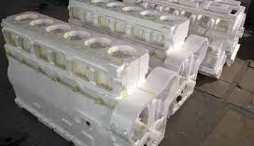
One of the core elements in lost foam casting is the foam pattern itself. We use H-S expandable polystyrene (EPS) beads with a density controlled between 22 g/L and 26 g/L. The molding process involves heating the beads at 40–50°C for about 3 minutes to ensure proper expansion and maturation. After demolding, the white patterns are inspected for dimensional accuracy, allowing a tolerance of -1 mm to +3 mm on critical dimensions. To prevent deformation, we employ support structures such as fiber rods and sand cores during pattern assembly. For instance, the oil pan’s wide edges are prone to warping, so we use定型卡板 (fixed templates) and fiber reinforcements to maintain shape integrity. The bonding of patterns is done with a combination of cold and hot adhesives to ensure uniform machining allowances, typically 3 mm for mounting surfaces and 2.5 mm for other areas.
The gating system design is crucial in lost foam casting to ensure proper metal flow and minimize defects. We adopted a top-pouring system with a hollow cylindrical sprue, divided into two inlet points to facilitate even filling. The cross-sectional area ratio is optimized as sprue:runner:ingate = 7:1:0.4, based on fluid dynamics principles. This design helps reduce turbulence and slag inclusion. The mathematical relationship for metal flow can be expressed using Bernoulli’s equation, where the velocity \( v \) of the molten metal is given by:
$$ v = \sqrt{2gh} $$
where \( g \) is the acceleration due to gravity and \( h \) is the height of the metal column. Additionally, the Reynolds number \( Re \) is considered to assess flow characteristics:
$$ Re = \frac{\rho v D}{\mu} $$
Here, \( \rho \) is the density of the molten iron, \( D \) is the hydraulic diameter, and \( \mu \) is the dynamic viscosity. Maintaining laminar flow (Re < 2000) minimizes oxide formation and dross. The coating application involves a water-based refractory material, applied by dipping and brushing to achieve a uniform thickness of at least 1.6 mm. Key coating parameters include viscosity control and drying cycles; for example, primary drying is done at 45°C for 10 hours, followed by secondary drying at 50°C for 14 hours, with touch-ups in corners to prevent weak spots.
Sand selection and compaction play a vital role in preventing defects like metal penetration. We use silica sand with a grain size of 0.4 mm to 0.8 mm, which provides adequate permeability and strength. During molding, the sand is compacted using vibration tables at frequencies of 40–45 Hz for a total time of at least 360 seconds. The vibration intensity ensures uniform density, especially in intricate areas where manual sand ramming is applied. The negative pressure during pouring is maintained at 0.04–0.05 MPa to prevent mold collapse and reduce gas-related defects. A higher negative pressure can exacerbate metal penetration, so precise control is essential. The relationship between sand compactness and defect incidence can be modeled using the following empirical formula for sand density \( \rho_s \):
$$ \rho_s = \rho_0 + k \cdot f \cdot t $$
where \( \rho_0 \) is the initial density, \( k \) is a constant, \( f \) is the vibration frequency, and \( t \) is the time. Optimal compaction reduces porosity and enhances heat dissipation.
Melting and composition control are critical for achieving desired metallurgical properties. The charge consists of scrap steel, returns, and alloying elements like ferrosilicon and ferromanganese. Low-sulfur carburizers are added to adjust carbon content. The target chemical composition for HT250 oil pans is summarized in Table 1, with carbon equivalent (CE) controlled between 3.8% and 4.1% to ensure good castability and mechanical strength. The carbon equivalent is calculated as:
$$ CE = C + \frac{Si + P}{3} $$
For our application, we maintain a Si/C ratio of 0.6–0.7 to promote pearlite formation and minimize free ferrite. Inoculation is performed both in the furnace and ladle using ferrosilicon-based inoculants, with a holding time of at least 5 minutes to allow for effective reaction. The pouring temperature is kept at 1,420–1,460°C, and the total pouring time per mold is limited to 3 minutes to prevent premature solidification. Post-pouring, the molds are held under negative pressure for 3 minutes to ensure complete solidification and reduce shrinkage defects.
| Element | Composition (%) |
|---|---|
| C | 2.9–3.1 |
| Si | 1.7–1.9 |
| Mn | 0.7–0.9 |
| P | ≤ 0.09 |
| S | ≤ 0.055 |
| Cr | 0.2–0.3 |
| Mg | 0.015–0.035 |
| Others | ≤ 0.12 |
Defect analysis revealed that deformation primarily occurred due to improper handling during pattern drying and molding. To address this, we implemented standardized drying protocols and used support fixtures. For metal penetration, increasing coating thickness and optimizing sand gradation proved effective. Dross formation was minimized by employing larger flux particles and improving slag removal techniques. Cold shuts and shrinkage porosity were mitigated by redesigning the gating system and adding blind risers at critical locations. The thermal dynamics during solidification can be described using Chvorinov’s rule for solidification time \( t_s \):
$$ t_s = k \cdot \left( \frac{V}{A} \right)^2 $$
where \( V \) is the volume of the casting, \( A \) is the surface area, and \( k \) is a constant dependent on mold material and metal properties. By positioning risers in areas with high V/A ratios, we enhanced feeding and reduced shrinkage defects.
Metallographic quality is closely tied to cooling rates and composition control. We observed that improper Si/C ratios led to insufficient pearlite content, below the required 10%. Adjusting the inoculation practice and using protective coatings during melting helped achieve a pearlitic matrix with minimal ferrite. The kinetics of pearlite formation can be expressed using the Avrami equation for phase transformation:
$$ f = 1 – \exp(-k t^n) $$
where \( f \) is the fraction transformed, \( k \) is a rate constant, and \( n \) is the Avrami exponent. By controlling cooling rates through mold design, we ensured consistent microstructure.
Implementation of these improvements involved multiple trial batches, each consisting of 32 oil pans. Results showed that using fiber rods for support reduced deformation-related scrap to under 3%. Optimized sand properties and vibration parameters decreased metal penetration incidents. The enclosed gating system with cylindrical sprues minimized slag entrapment and cold shuts. Composition adjustments ensured that pearlite content met standards, with microstructures showing over 90% pearlite. Overall, the yield improved to 96%, demonstrating the effectiveness of the lost foam casting process refinements. In conclusion, lost foam casting offers a viable solution for complex components like oil pans, but success hinges on meticulous control of every process step. Future work could focus on automating pattern assembly and real-time monitoring of casting parameters to further enhance efficiency and consistency in lost foam casting applications.
To summarize the key process parameters, Table 2 provides an overview of the optimized settings for lost foam casting of oil pans. These parameters were derived from empirical data and theoretical models, ensuring robust performance in industrial settings.
| Parameter | Value |
|---|---|
| Foam Density | 22–26 g/L |
| Molding Temperature | 40–50°C |
| Coating Thickness | ≥ 1.6 mm |
| Drying Time (Primary) | 10 h at 45°C |
| Drying Time (Secondary) | 14 h at 50°C |
| Sand Grain Size | 0.4–0.8 mm |
| Vibration Frequency | 40–45 Hz |
| Vibration Time | ≥ 360 s |
| Negative Pressure | 0.04–0.05 MPa |
| Pouring Temperature | 1,420–1,460°C |
| Pouring Time per Mold | ≤ 3 min |
| Si/C Ratio | 0.6–0.7 |
| Carbon Equivalent | 3.8–4.1% |
In terms of economic and environmental benefits, lost foam casting reduces material waste and energy consumption compared to traditional sand casting. The ability to produce near-net-shape components minimizes machining, leading to lower costs and shorter lead times. As industries strive for sustainability, lost foam casting stands out as a green technology, aligning with global trends in manufacturing. Our experience underscores the importance of continuous improvement and cross-functional collaboration in mastering lost foam casting techniques. By sharing these insights, we hope to contribute to the broader adoption of lost foam casting in various sectors, from automotive to heavy machinery.