
As an engineer deeply involved in the field of advanced casting technologies, I have always been fascinated by the intricacies of lost foam casting. This process, where a foam pattern is vaporized by molten metal to form a casting, offers unparalleled design freedom and precision. However, the success of lost foam casting hinges critically on the quality and design of the foam pattern itself. In this article, I will delve into the comprehensive design process for the block molding of a lost foam pattern, specifically for a large ductile iron mechanical base. Drawing from practical experience and leveraging modern CAD tools like Pro/ENGINEER (Pro/E), I aim to outline a methodology that enhances efficiency and reliability in pattern design for complex castings. The principles discussed here are universally applicable in lost foam casting projects, emphasizing systematic planning and digital simulation.
The foundation of any lost foam casting project is a thorough analysis of the intended casting. The component in focus is a substantial mechanical base, required in batch production but initially prototyped as a single unit. Its material specification is QT450 ductile iron, conforming to standards like GB/T1348-2009, which dictates mechanical properties and quality benchmarks. The dimensional tolerances and machining allowances are derived from GB/T6414-1999, ensuring the final product meets rigorous industrial specifications. From a structural standpoint, the base is a near-symmetric entity with considerable complexity. Its external envelope measures 1800 mm in length, 1100 mm in width, and 800 mm in height. The volume is approximately 3.34 × 10⁵ cm³, leading to a weight of roughly 2.44 × 10³ kg. Such dimensions immediately signal challenges in pattern manufacturing, handling, and casting integrity. The geometry includes reinforcing ribs, hollow sections, and various mounting features, all of which must be accurately replicated in foam.
When transitioning from a casting design to a foam pattern for lost foam casting, one cannot simply copy the part geometry. The pattern must be engineered considering the unique constraints and behaviors of the foam material during both molding and the casting process itself. My approach always begins with defining the overall pattern design parameters, which include shrinkage allowances, machining additions, and strategic reinforcement. These factors collectively ensure the final casting shrinks correctly to size, has sufficient material for post-casting machining, and possesses the structural soundness to withstand the rigors of the casting process without distortion or failure.
The total shrinkage allowance for the pattern is a composite of two primary factors: the contraction of the foam material itself and the solidification shrinkage of the ductile iron metal. For the foam, I typically use STMMA (a copolymer of styrene and methyl methacrylate), which exhibits a free shrinkage rate in the range of 0.1% to 0.2% under normal conditions. After considering the molding process parameters—such as cooling time and pressure in the pre-expander and molding machine—a practical value of 0.15% is adopted for the foam. The ductile iron, QT450, has a typical linear solidification shrinkage of about 0.9%. Therefore, the combined shrinkage factor applied to the pattern’s nominal dimensions is the sum of these effects. This can be expressed by the formula:
$$ S_{total} = S_{foam} + S_{metal} $$
Where \( S_{foam} = 0.0015 \) and \( S_{metal} = 0.009 \). Thus,
$$ S_{total} = 0.0015 + 0.009 = 0.0105 \text{ or } 1.05\% $$
Every linear dimension on the pattern must be scaled up by this factor. In Pro/E, this is efficiently handled by applying a global scale factor to the solid model before detailed pattern design commences.
Machining allowances are added to surfaces designated for post-casting machining. According to the CT6-CT8 dimensional accuracy achievable with lost foam casting, the allowances are selected from standard tables. For planes, allowances are applied based on whether machining is single-sided or double-sided. For holes, a double-sided allowance is applied. A uniform additional offset of 1 mm is applied to all non-machined surfaces to account for minor surface imperfections and ensure clean geometry after casting. This step is crucial in lost foam casting to guarantee that the casting meets dimensional specifications after final machining.
Reinforcement in the form of casting ribs is often necessary to prevent hot tearing, reduce stress concentration, and enhance the overall stiffness of the casting during solidification. For this base, four symmetrically arranged ribs are designed at the bottom of the central cavity section. These ribs connect the bottom plate to the side walls, effectively mitigating potential cracks. The design of these ribs follows standard guidelines to avoid creating new thermal nodes that could lead to shrinkage defects. The cross-sectional area of a rib is typically 0.6 to 0.8 times the thickness of the wall it joins. This relationship can be generalized as:
$$ A_{rib} = k \cdot t_{wall} $$
where \( k \) is a factor between 0.6 and 0.8, and \( t_{wall} \) is the nominal wall thickness. For this base, with wall thicknesses around 20 mm, the rib cross-section is designed accordingly.
With these foundational parameters set, I proceed to create the complete 3D model of the foam pattern using Pro/E. This digital prototype incorporates all shrinkage, machining allowances, and rib designs. It serves as the master reference for all subsequent steps. The model reveals a complex, monolithic shape that is impractical to produce as a single foam piece due to limitations in mold design, foam molding dynamics, and ease of handling. This leads to the core of this discussion: block molding design, or dividing the single pattern into multiple, manufacturable foam blocks that will be assembled later.
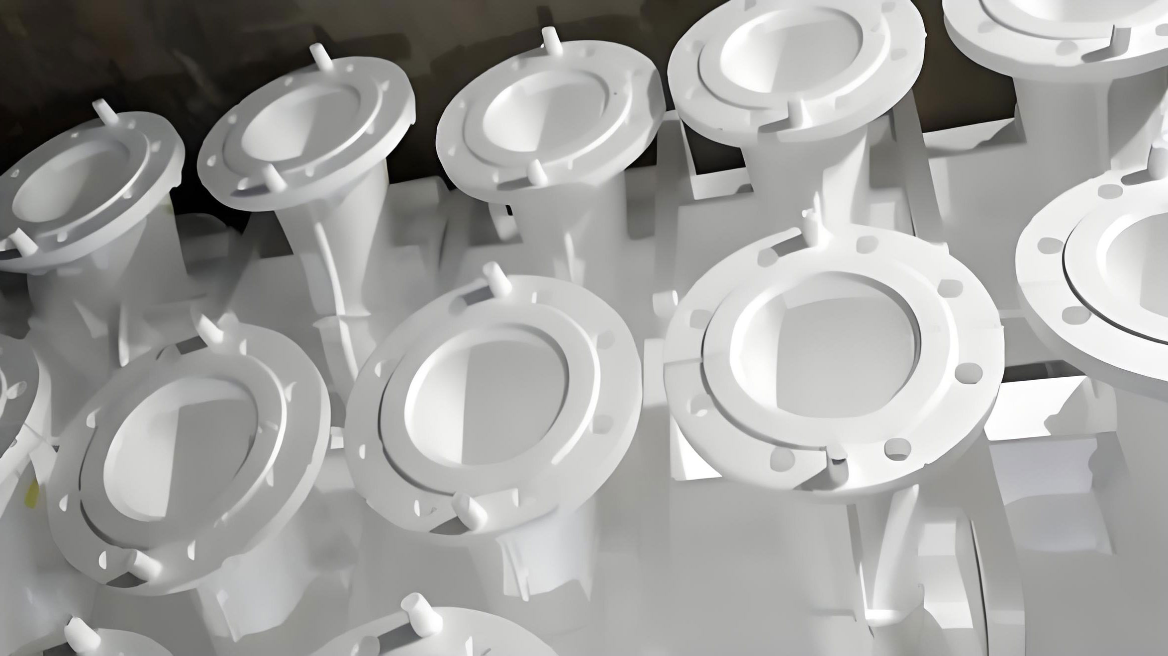
The division of a complex pattern into blocks is a critical step in lost foam casting. Poor partitioning can lead to difficulties in mold manufacturing, increased pattern assembly time, weak joints that fail during mold filling, and ultimately, defective castings. Over years of practice, I have distilled a set of guiding principles for effective block molding design in lost foam casting:
- Simplify Block Geometry: Each individual block should have a shape that is as simple as possible. This simplifies the corresponding mold cavity, reduces the need for complex sliding cores or lifters in the mold, and lowers manufacturing cost. Ideally, blocks should be prismatic or feature simple curves.
- Minimize Number of Blocks: While simplification is key, the total number of blocks should be kept to the absolute minimum. Each additional block introduces an assembly interface—a potential source of dimensional error, increased labor, and a location for gas generation during casting. There is always a trade-off, but the goal is to find the balance where blocks are simple yet few.
- Minimize Glue Joint Area: The interfaces where blocks are glued together should be designed to have the smallest practical area while maintaining sufficient strength. A large glue area requires more adhesive, increases curing time, and can lead to greater volumetric displacement of foam when the glue expands, affecting dimensional accuracy.
- Preserve Geometric Integrity: Critical geometric features, especially continuous curves and radii, should not be split across a glue joint. If a smooth radius is cut by a joint, it becomes very challenging to achieve a seamless appearance after gluing, which can transfer as a seam line on the final casting.
Applying these principles to the ductile iron base pattern, I arrived at a division scheme comprising nine physical foam blocks. However, due to symmetry, there are only six unique block designs. This reuse of block designs further economizes on mold fabrication. The breakdown is summarized in the table below:
| Block ID | Description | Material | Quantity per Pattern | Key Characteristics |
|---|---|---|---|---|
| 1 | Central Core Block | STMMA | 2 | Forms the main cavity; features hollow sections to reduce foam mass. |
| 2 | Top Cover Block | STMMA | 1 | Seals the top of the central cavity; includes mounting boss details. |
| 3 | Side Panel Block | STMMA | 2 (Left & Right) | Forms the large vertical side walls; relatively flat geometry. |
| 4 | End Closure Block | STMMA | 2 (Front & Rear) | Closes the ends of the structure; includes flange features. |
| 5 | Front Access Block | STMMA | 1 | Includes complex cut-outs; designed with a lap joint for strength. |
| 6 | Rear Panel Block | STMMA | 1 | Similar to an end block but with internal provisions for core assembly. |
The virtual assembly of these blocks in Pro/E is an invaluable step. It allows for interference checking, verification of glue joint fits, and simulation of the assembly sequence. The exploded view clearly shows how the blocks relate to each other, and the rendered assembly confirms the integrity of the final pattern shape. This digital prototyping is a cornerstone of efficient lost foam casting pattern design.
Once the blocks are defined, the design must meticulously address how they will be joined. In this project, manual gluing with cold-setting adhesive is chosen for cost-effectiveness and operational flexibility. This choice directly influences the block design in three significant ways.
First, the glue joint thickness allowance must be incorporated. The adhesive layer has a finite thickness, which, if not accounted for, will make the assembled pattern oversized. For cold glue, based on empirical data, the typical “glue negative” or reduction required per mating surface is 0.2 mm. Since each block contributes one mating face to a joint, each face is recessed or offset by 0.1 mm from its nominal position. In Pro/E, this is achieved by creating a slight offset surface on the joining faces during the block modeling phase. The effective joint gap \( g \) after gluing can be approximated by:
$$ g = 2 \times \delta_{block} + t_{adhesive} $$
where \( \delta_{block} \) is the recession per block face (0.1 mm) and \( t_{adhesive} \) is the final adhesive film thickness (≈0.2 mm). Ideally, \( g \) should be close to zero to maintain dimensions, hence the need for precise recession.
Second, joint strength is paramount to prevent the pattern from coming apart during the vigorous vibration of the sand filling process in lost foam casting. Two strategies are employed. For joints where the glue area is inherently small relative to the block size, such as the long, thin interface between the central core blocks and the bottom structure, reinforcing tape is applied over the glued seam after assembly. This tape, compatible with the coating process, adds significant tensile and shear strength. Furthermore, for multi-block intersections that create structurally weak points, the block design incorporates lap joints instead of simple butt joints. For instance, the Front Access Block (Block 5) is designed to overlap with the mating faces of the Central Core Block and the Top Cover Block. This overlap increases the glue area in a shear-loaded configuration, greatly enhancing joint integrity. The strength of a lap joint in shear \( \tau_{lap} \) can be roughly compared to a butt joint \( \tau_{butt} \) by the area multiplier:
$$ \frac{\tau_{lap}}{\tau_{butt}} \approx \frac{A_{lap}}{A_{butt}} $$
where \( A_{lap} \) is the overlapping shear area, which is typically several times larger than the cross-sectional area of a butt joint.
Third, a key advantage of lost foam casting is the ability to reduce gas generation by selectively hollowing out thick sections of the foam pattern. During metal pouring, the foam vaporizes, and excessive foam mass in a localized area can produce large volumes of gas faster than the coating can vent, leading to defects like porosity or incomplete filling. Therefore, in thick portions of the pattern, such as the massive central core blocks (Block 1), internal voids are designed. These voids significantly reduce the volume of foam material without compromising the external shape or the pattern’s structural strength during handling. The reduction in gas volume \( \Delta V_{gas} \) is directly proportional to the volume of foam removed \( V_{removed} \), assuming complete gasification:
$$ \Delta V_{gas} = \rho_{gas} \cdot V_{removed} $$
where \( \rho_{gas} \) is the gas yield per unit volume of foam (a property of STMMA). This design consideration is critical for producing sound castings in lost foam casting.
The assembly sequence of the blocks is not trivial and must be planned during the design phase to ensure practicality. For this base pattern, the sequence is as follows:
- Join the two Central Core Blocks (1): These are glued together along their vertical mid-plane to form the core of the structure.
- Attach the Top Cover Block (2): This block is glued onto the top of the assembled central core.
- Glue the Side Panel Blocks (3): The left and right side panels are attached to the central assembly.
- Attach the End Closure Blocks (4): The front and rear end blocks are glued in place. Note: At this stage, the “front” position might be temporarily left open for internal access.
- Internal Preparation for Rear Block (6): Before attaching the Rear Panel Block, internal components must be placed. For this casting, a steel tube needs to be inserted through a hole in the rear block to form a cored passage in the final casting. This tube is positioned, and the internal cavity of the pattern is coated with the refractory wash. After the coating dries, the cavity is filled and hand-rammed with resin sand to create a solid core. This hybrid “full mold + sand core” approach is sometimes used in lost foam casting for complex internal features that are difficult to form with foam alone.
- Attach the Rear Panel Block (6): With the internal core prepared, the rear block is glued into place, encapsulating the sand core and tube.
- Finally, attach the Front Access Block (5): This block, designed with a lap joint, is glued last to complete the pattern assembly.
Throughout this assembly process, constant dimensional checks are performed using templates or digital measuring devices against the Pro/E model to ensure accuracy. The use of Pro/E software in this entire workflow cannot be overstated. Its parametric modeling capabilities allow for rapid iteration of block designs. The assembly module enables virtual fit-up and clash detection, saving tremendous time and physical material. The software also generates precise 2D drawings for each unique block, which become the direct input for CNC machining of the mold cavities or for fabricating model plates for traditional pattern making. This digital thread from casting design to foam block design to mold design is what makes modern lost foam casting competitive for complex components.
To further generalize the design parameters and decisions involved, I find it helpful to summarize key relationships in a formalized manner. The following table encapsulates major design variables and their typical values or formulas for a ductile iron lost foam casting project like this base.
| Parameter | Symbol | Typical Value / Formula | Remarks |
|---|---|---|---|
| Total Linear Shrinkage | \( S_{total} \) | \( S_{foam} + S_{metal} \) | Applied as a scale factor to nominal part dimensions. |
| Foam Material Shrinkage | \( S_{foam} \) | 0.0015 (0.15%) for STMMA | Depends on bead type, molding cycle. |
| Metal Shrinkage (Ductile Iron) | \( S_{metal} \) | 0.009 (0.9%) | Depends on alloy and cooling rate. |
| Machining Allowance (CT7) | \( MA \) | From std. tables (e.g., 2-3 mm per face) | Added to relevant surfaces after scaling. |
| Non-machined Surface Enlargement | \( \delta_{nm} \) | 1.0 mm | Uniform offset for as-cast surfaces. |
| Glue Joint Allowance per Face | \( \delta_{glue} \) | 0.1 mm for cold glue | Recession from nominal joint surface. |
| Adhesive Layer Thickness | \( t_{adhesive} \) | ≈0.2 mm | Target final thickness after curing. |
| Rib Section Factor | \( k \) | 0.6 – 0.8 | Multiplier for adjacent wall thickness. |
| Foam Density (Expanded) | \( \rho_{foam} \) | 20-25 kg/m³ for STMMA | Affects pattern weight and gas volume. |
| Gas Yield per Unit Foam Volume | \( \rho_{gas} \) | Material-specific constant | Drives hollowing-out decisions for thick sections. |
In conclusion, the block molding design for a lost foam pattern is a multidisciplinary exercise that blends understanding of casting metallurgy, foam material science, adhesive chemistry, and precision manufacturing. The case of the ductile iron base vividly illustrates that successful lost foam casting is not merely about making a foam replica of a part. It involves a deliberate, step-by-step engineering process where digital tools like Pro/E play a transformative role. By adhering to principles of simplification, minimization, and strength optimization during block division, and by meticulously designing for glue joints and gas management, one can reliably produce complex, high-quality foam patterns. These patterns are the heart of the lost foam casting process, directly dictating the quality of the final metal component. The methodology outlined here, centered on digital prototyping and systematic design rules, significantly enhances efficiency, reduces trial-and-error, and provides a solid foundation for the design and manufacturing of the block molds themselves. As lost foam casting technology continues to evolve, such integrated digital-physical approaches will become even more critical in tackling increasingly intricate casting challenges across various industries.