
In my extensive experience in the foundry industry, I have dedicated significant effort to advancing the casting processes for critical automotive components. One of the most challenging projects I undertook involved the development of a high-performance clutch flywheel made from spheroidal graphite cast iron. This component is integral to the transmission system of premium vehicles, where it functions as a rotational mass that stores kinetic energy and facilitates the smooth engagement and disengagement of the engine and drivetrain. The demanding quality requirements, including exceptional toughness, dimensional stability, and freedom from defects, necessitated a meticulous redesign of the casting process. This article details my first-person journey in designing, simulating, and implementing an innovative casting process for this high-toughness spheroidal graphite cast iron clutch flywheel, culminating in a successful batch production that meets stringent specifications.
The primary technical specifications for the clutch flywheel were exceptionally rigorous. The material had to exhibit a nodularity exceeding 85%, with graphite particles sized between 5 to 7 grade according to standard classifications, and the complete absence of flake graphite. Furthermore, the microstructure was required to have less than 1% carbides and cementite. The mechanical properties targets were a tensile strength (Rm) of at least 500 MPa, a yield strength (Rp0.2) of at least 320 MPa, and an elongation (A) of 12% or more, with a hardness range of 170 to 230 HB. A mandatory heat treatment process was specified to relieve residual stresses, ensure dimensional stability after machining (preventing deviations in perpendicularity, flatness, and related dimensions), enhance elongation, and eliminate any traces of carbides or cementite. Surface defects such as sand inclusions or slag holes that could impede machining or assembly were strictly prohibited. Internally, the casting had to be free from cracks and shrinkage porosity. Achieving all these for a complex, thin-walled component like a flywheel presented a formidable engineering challenge.
My initial casting process design, based on conventional wisdom for spheroidal graphite cast iron, utilized a DISA 231 vertical flaskless molding machine. The mold plate dimensions were 650 mm by 535 mm. This initial design, as illustrated in the process flow diagram, adopted a one-cavity-per-mold approach. The gating system included a pouring cup, a runner, and ingates leading to a single overheating riser that fed the casting. However, this design soon revealed critical limitations. The geometry of the flywheel featured significant variation in wall thickness. Particularly problematic was a sharp corner junction between the outer rim and the disc face, which had a mere 5 mm thickness. This thin section acted as a bottleneck, severely restricting the feeding efficiency of the riser and leading to persistent shrinkage porosity in the thicker sections of the casting. Furthermore, the single-cavity setup resulted in low productivity and a suboptimal metal yield of only around 38%.
Determined to overcome these hurdles, I spearheaded a complete redesign of the process. The core innovation was the shift from one to two castings per mold without altering the existing molding equipment. This was achieved by employing a shared partition core between the two mold halves (cope and drag). Within this partition core, I integrated three strategically placed chills, each positioned 4 mm from the casting surface. These chills, made of cast iron, served as external cooling agents to promote directional solidification. The two castings shared a common overheating riser, fed by a redesigned gating system. This new system was conceived as a pressure-reducing and slag-trapping system. Specifically, the ingate thickness connecting to the riser was precisely controlled at 2 mm. This thin section reduces the metallostatic pressure during pouring, minimizes turbulence, and improves slag capture efficiency. The partition core itself was a resin-coated sand core produced via a hot-box process. After production and cooling, pre-dried chills were placed into designated cavities in the lower half of the core. The upper and lower core halves were then assembled using a dedicated fixture to form a single, integrated core unit ready for molding.
The advantages of this novel process for spheroidal graphite cast iron components were multi-fold. First, the chills provided intense localized cooling, effectively eliminating shrinkage porosity by ensuring progressive solidification from the thin sections towards the riser. Second, productivity doubled from approximately 400 pieces per hour to 800 pieces per hour. The metal yield improved dramatically from 38% to 55%, representing substantial material and cost savings. Third, the减压浇注系统 (pressure-reducing gating system) significantly reduced the incidence of slag and sand inclusion defects. Finally, the reduced consumption of green molding sand per unit of production lowered overall foundry operating costs. To validate this design before committing to expensive tooling and trials, I employed advanced numerical simulation software. Using a high-performance workstation, I converted the 3D CAD models into STL format and performed a finite element analysis. The simulation involved meshing the system into over 9.8 million elements. I input key process parameters such as pouring temperature, pouring time, chemical composition of the spheroidal graphite cast iron, and material boundary conditions including heat transfer coefficients. The simulation ran for approximately 8 hours, modeling the filling, solidification, and prediction of potential defects like shrinkage and inclusions.
The simulation results were highly encouraging. The temperature field distribution clearly showed the chilling effect guiding solidification fronts. The shrinkage porosity prediction module indicated that the new design with chills effectively moved the isolated liquid pools and potential shrinkage to the shared riser, leaving the casting itself sound. This virtual validation gave me the confidence to proceed to physical prototyping and production. The solidification process in casting is often governed by Chvorinov’s rule, which can be expressed as:
$$ t_f = k \left( \frac{V}{A} \right)^n $$
where \( t_f \) is the solidification time, \( V \) is the volume of the casting section, \( A \) is its surface area, \( k \) is a mold constant, and \( n \) is an exponent typically close to 2. For the thin corner section (5mm) versus the thicker hub, the modulus \( \frac{V}{A} \) is much smaller, leading to rapid solidification. The chill plates effectively increase the local \( A \), further reducing \( t_f \) and ensuring this area solidifies first, creating a feeding path towards the riser in the thicker sections. This principle was central to my design strategy for this spheroidal graphite cast iron casting.
The melting and treatment of the spheroidal graphite cast iron was equally critical to achieving the target properties. I used a medium-frequency induction furnace with a basic lining. The charge consisted of 50% low-manganese, low-chromium steel scrap (clean, rust-free punching scraps), 45% returns (gates and scrapped castings of QT500-7 grade, thoroughly shot-blasted), and 5% pig iron (Q10 grade). High-purity, low-sulfur graphite carburizer was added with the charge to achieve the target carbon content. Precise control of the base iron chemistry before treatment was paramount. I aimed for a composition that would allow the final heat-treated part to exceed the specified grade by about 20% in the as-cast state to compensate for any potential strength loss during annealing. The target base iron composition is summarized in Table 1.
| Element | Target Range (wt.%) |
|---|---|
| Carbon (C) | 3.70 – 3.85 |
| Silicon (Si) | 1.70 – 1.95 |
| Manganese (Mn) | ≤ 0.40 |
| Copper (Cu) | ≤ 0.40 |
| Phosphorus (P) | ≤ 0.05 |
| Sulfur (S) | ≤ 0.025 |
Upon reaching a temperature of 1500-1520°C, the metal was tapped into a treatment ladle. A primary inoculation with 0.30% FeSi alloy (2.8-4.0 mm granules) was performed during tapping. The key spheroidization treatment was carried out using a wire-feeding method with a high-Mg, low-rare earth cored wire. Maintaining a low sulfur level was crucial for efficient Mg recovery and to avoid excessive slag formation. The wire feeding parameters were tightly controlled, as detailed in Table 2. The reaction was conducted under a covered ladle to minimize Mg loss through oxidation and flare.
| Parameter | Value/Range |
|---|---|
| Pre-treatment Temperature | 1465 – 1485 °C |
| Wire Length | 14.2 ± 0.15 m |
| Wire Feeding Speed | 120 ± 0.15 m/min |
| Reaction Time | 45 – 60 s |
| Post-treatment Temperature | 1430 – 1450 °C |
| Wire Addition (Mg) | ~0.65% (of iron weight) |
After spheroidization, the metal was transferred to a pouring ladle, where a secondary inoculation of 0.30% FeSi (0.5-2.0 mm) was added during the transfer. Finally, a late-stream inoculation of 0.20% FeSi (0.2-0.6 mm) was performed during the actual pouring into the molds. The entire treatment sequence was designed to maximize nodule count and ensure a uniform, fine graphite structure in the final spheroidal graphite cast iron. The pouring temperature was maintained between 1415°C and 1365°C, with a single mold filled in 7-9 seconds. The total pouring time for a ladle was kept under 8 minutes to prevent fading of the inoculation effect. The residual magnesium content was controlled within 0.030% to 0.045% to ensure good nodularity while avoiding excessive Mg that could promote shrinkage tendency.
The heat treatment process was designed to relieve casting stresses, decompose any minor carbides formed in the thin sections during solidification, and promote the formation of ferrite to boost ductility. I selected a sub-critical annealing process. The castings were loaded into a car-bottom furnace and heated to a soaking temperature of 600°C. They were held at this temperature for 2 hours to allow for stress relaxation and carbide decomposition. The furnace was then shut off, and the castings were cooled slowly inside the furnace at a controlled rate of 60-80°C per hour. This slow cool is vital to prevent the introduction of new thermal stresses. Once the temperature reached 300°C, the castings were unloaded and allowed to cool in air to ambient temperature. The kinetics of carbide decomposition during annealing can be described by an Arrhenius-type equation related to diffusion:
$$ D = D_0 \exp\left(-\frac{Q}{RT}\right) $$
where \( D \) is the diffusion coefficient, \( D_0 \) is a pre-exponential factor, \( Q \) is the activation energy for carbon diffusion in iron, \( R \) is the gas constant, and \( T \) is the absolute temperature. The chosen temperature of 600°C provides sufficient thermal energy for carbon diffusion to facilitate the dissolution of carbides into austenite (and subsequent transformation to ferrite and graphite upon cooling) without risking excessive grain growth or phase transformations that could reduce toughness in this spheroidal graphite cast iron.
After implementing the new process and heat treatment cycle, I conducted rigorous testing on sample castings taken from production batches. The chemical composition was verified using optical emission spectrometry on samples machined from the castings themselves. The results, shown in Table 3, confirm the consistency and appropriateness of the chemistry for high-toughness spheroidal graphite cast iron.
| Sample | C | Si | Mn | Cu | P | S | Cr | Mgres |
|---|---|---|---|---|---|---|---|---|
| 1 | 3.625 | 2.573 | 0.386 | 0.351 | 0.043 | 0.016 | 0.020 | 0.039 |
| 2 | 3.885 | 2.554 | 0.380 | 0.349 | 0.042 | 0.011 | 0.021 | 0.040 |
| 3 | 3.690 | 2.523 | 0.387 | 0.362 | 0.051 | 0.012 | 0.020 | 0.039 |
| 4 | 3.602 | 2.544 | 0.382 | 0.345 | 0.043 | 0.015 | 0.022 | 0.041 |
| 5 | 3.647 | 2.538 | 0.384 | 0.357 | 0.044 | 0.014 | 0.024 | 0.042 |
Mechanical properties were evaluated on separately cast test bars or machined specimens from the flywheel body after heat treatment. Tensile testing was performed using a servo-hydraulic universal testing machine. The results, presented in Table 4, not only meet but in many cases exceed the specified requirements, demonstrating the success of the integrated process for producing high-integrity spheroidal graphite cast iron.
| Sample | Tensile Strength (MPa) | Yield Strength (MPa) | Elongation (%) | Surface Hardness (HB) | Core Hardness (HB) |
|---|---|---|---|---|---|
| 1 | 545 | 396 | 15.0 | 210 | 192 |
| 2 | 540 | 392 | 14.0 | 205 | 189 |
| 3 | 550 | 400 | 15.5 | 215 | 198 |
| 4 | 555 | 405 | 13.0 | 219 | 201 |
| 5 | 545 | 395 | 14.0 | 204 | 187 |
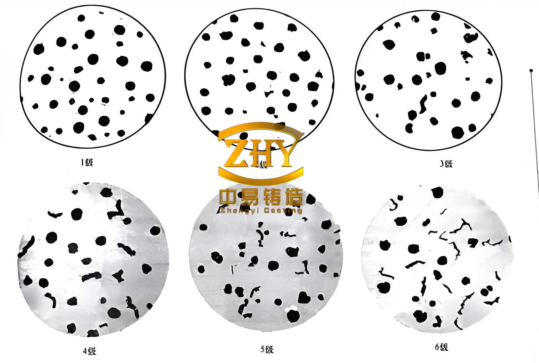
Metallographic examination was conducted according to ASTM E1245. The analysis revealed a nodularity of 90%, with graphite size predominantly at grades 5-6. No flake graphite was observed. The matrix structure consisted of a fine mixture of ferrite and pearlite, with no detectable carbides or cementite, as required. This excellent microstructure is the direct result of the precise melting, inoculation, and heat treatment practices developed for this spheroidal graphite cast iron component. The relationship between ultrasonic velocity and nodularity in spheroidal graphite cast iron is well-established and was used for non-destructive testing. The velocity \( v \) in a material is given by:
$$ v = \sqrt{\frac{E}{\rho}} $$
where \( E \) is the dynamic modulus of elasticity and \( \rho \) is the density. In spheroidal graphite cast iron, \( E \) increases with higher nodularity and more perfect spheroidal graphite shapes. We established an acceptance range of 5530 to 5680 m/s for the ultrasonic velocity measured on critical sections of the flywheel, which correlated reliably with a nodularity above 85%. All production castings passed this test.
A comprehensive non-destructive evaluation (NDE) regime was implemented. 100% visual inspection after shot blasting confirmed the absence of surface defects like sand and slag holes. Radiographic testing using a real-time X-ray system confirmed that internal discontinuities were within the strict limits of ASTM E689 Class 1, far surpassing the Class 2 requirement. Magnetic particle inspection on all edges and critical surfaces detected no cracks or hot tears. Additionally, destructive sampling involving sectioning through suspected hot spots followed by liquid penetrant testing (dye penetrant) revealed no subsurface shrinkage or micro-porosity. These results collectively validated the effectiveness of the chill design and feeding system in producing sound castings from spheroidal graphite cast iron.
In conclusion, the redesigned casting process for the high-toughness spheroidal graphite cast iron clutch flywheel has proven to be a resounding success. By innovatively implementing a two-cavity mold with a partitioned core containing chills, a pressure-reducing gating system, and optimizing the entire metallurgical and thermal processing chain, I was able to overcome the challenges of shrinkage porosity, low yield, and defect incidence. The process, validated through sophisticated computer simulation and extensive physical testing, consistently produces castings that meet all specified mechanical, microstructural, and quality standards. The successful batch production of this spheroidal graphite cast iron component demonstrates the power of integrated process design. Looking ahead, to prepare for potential material grade upgrades (e.g., from QT500-12 to QT500-18), further research is warranted. This would involve fine-tuning the chemistry, particularly the balance of silicon and copper, and exploring modified heat treatment cycles to push elongation beyond 18% while maintaining the high strength and flawless quality that this process for spheroidal graphite cast iron has already achieved. The journey has reinforced my belief that continuous innovation in foundry engineering is key to meeting the evolving demands of high-performance automotive components.