
In my experience working with small and medium-sized foundries, the production of complex gray iron castings, such as cylinder heads, using lost foam casting (LFC) presents significant challenges. Gray iron castings are widely used in automotive and industrial applications due to their excellent castability, machinability, and damping capacity. However, the intricate geometry of cylinder heads—featuring internal passages, thin walls, and complex cores—makes traditional sand casting labor-intensive and prone to defects like poor surface finish and high machining allowances. Lost foam casting offers a promising alternative by eliminating cores and parting lines, reducing machining, and improving surface quality. Yet, for foundries with limited resources, achieving consistent quality in gray iron castings via LFC requires careful process调试. This article shares my firsthand insights and systematic approaches to debugging the LFC process for gray iron cylinder heads, incorporating technical analyses, tables, and formulas to guide practitioners.
The fundamental principle of lost foam casting involves using a foam pattern (typically expanded polystyrene) that is coated with a refractory coating, embedded in dry sand, and then vaporized by molten metal during pouring. For gray iron castings, the process must account for the high carbon equivalent and fluidity of iron, as well as the substantial gas generation from foam decomposition. In cylinder head production, common defects include cold shuts, gas porosity, carbon inclusions, and coating residues, which compromise sealing and mechanical properties. Through iterative trials, I have identified key factors: pattern density, gating design, coating properties, sand compaction, and pouring parameters. The following sections delve into each aspect, with empirical data and theoretical models to support process optimization.
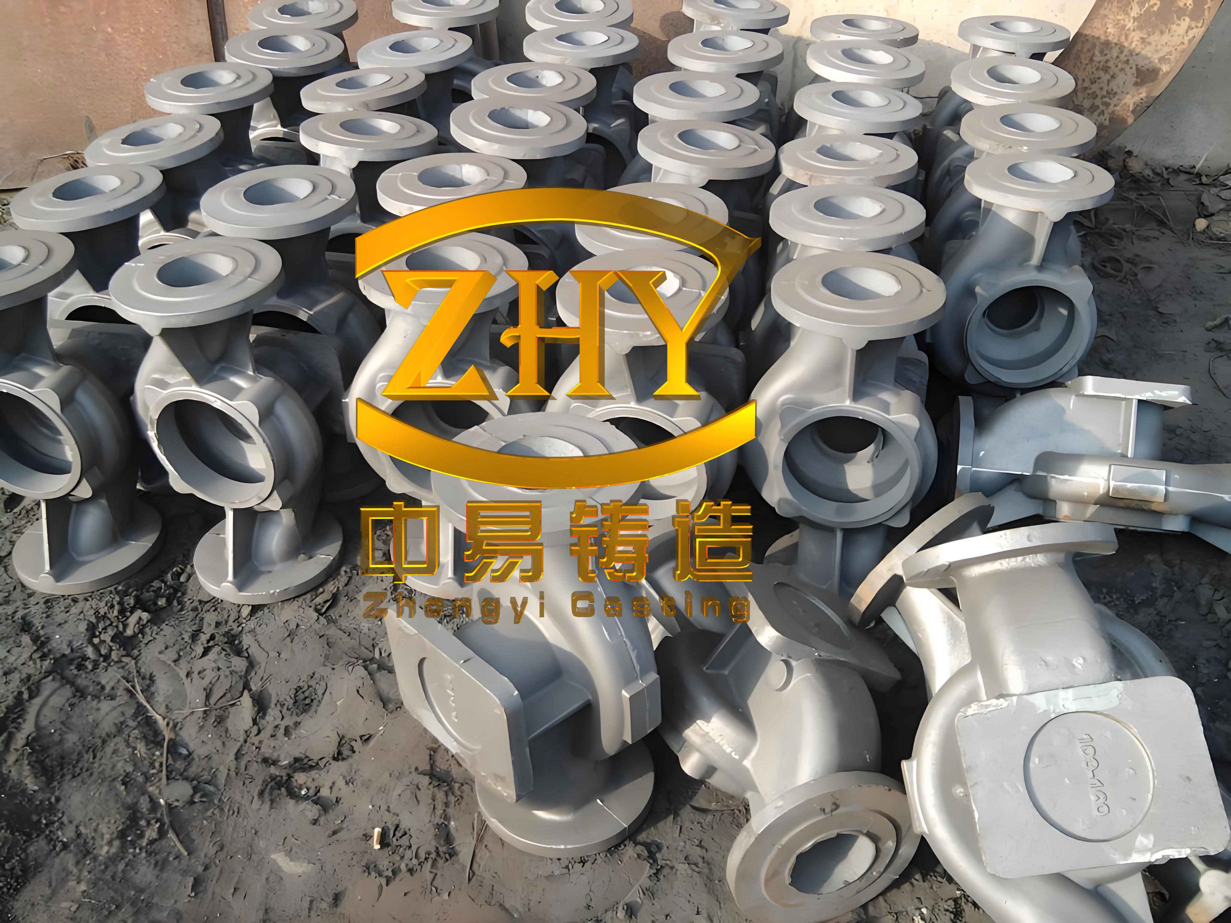
Pattern design is critical for gray iron castings. Cylinder head patterns are often assembled from multiple foam segments to capture complex features. The pattern density, typically around 0.035–0.05 g/cm³, influences gas evolution during pouring. Higher densities increase gas volume, risking defects if not managed. The gas generation rate can be modeled using the ideal gas law and decomposition kinetics. For a foam pattern of density $\rho_p$ (g/cm³) and volume $V_p$ (cm³), the total gas produced $G$ (cm³) at pouring temperature $T$ (K) is approximated by:
$$ G = \frac{nRT}{P} $$
where $n$ is moles of gas from foam decomposition, $R$ is the gas constant, and $P$ is pressure. Assuming polystyrene decomposes to volatile hydrocarbons, $n$ can be estimated from mass loss. To minimize gas-related issues, I recommend keeping pattern density below 0.04 g/cm³ for gray iron castings. Adhesive usage must be controlled, as excess adhesive adds to gas generation. Table 1 summarizes typical pattern parameters for cylinder heads.
| Parameter | Value Range | Influence on Gray Iron Castings |
|---|---|---|
| Pattern Density (g/cm³) | 0.035–0.045 | Higher density increases gas volume, risk of porosity |
| Segment Number | 3–5 pieces | More segments raise adhesive use and misalignment risk |
| Adhesive Type | Water-based glue | Minimizes gas emission compared to solvent-based |
| Assembly Tolerance (mm) | ±0.2 | Critical for dimensional accuracy of final castings |
Gating system design directly affects filling behavior and defect formation in gray iron castings. I explored two orientations: horizontal and vertical pouring. Horizontal placement simplifies sand filling but may lead to cold shuts on upper surfaces due to heat loss. Vertical placement enhances thermal gradient but complicates sand compaction. The gating must ensure rapid, turbulent-free filling to prevent mistruns. For gray iron, the pouring time $t$ (s) can be estimated using Bernoulli’s equation and fluid dynamics:
$$ t = \frac{V_c}{A_g \cdot v} $$
where $V_c$ is cavity volume (cm³), $A_g$ is total gating area (cm²), and $v$ is flow velocity (cm/s). Velocity depends on head pressure and friction losses. I designed a stepped gating system with a hollow sprue to accelerate metal delivery. The hollow sprue reduces heat loss and maintains superheat, crucial for gray iron castings with high fluidity but prone to chilling. The gating ratio (sprue:runner:ingate) was set to 1:1.5:2.0 to promote pressurized flow. Table 2 compares gating designs for the two orientations.
| Orientation | Sprue Type | Ingate Number | Gating Ratio | Expected Fill Time (s) |
|---|---|---|---|---|
| Horizontal | Solid | 2 | 1:1.2:1.5 | 8–10 |
| Vertical | Hollow | 3 | 1:1.5:2.0 | 6–8 |
Coating formulation and application are paramount for gray iron castings. The coating must withstand thermal shock, provide permeability for gas escape, and resist erosion. I used a water-based coating with refractory fillers (e.g., zircon, alumina) and binders (e.g., bentonite, latex). Coating thickness $d_c$ (mm) influences gas permeability and strength. An optimal range of 0.5–1.0 mm balances these factors. The permeability $k$ (cm²) can be expressed as:
$$ k = \frac{\phi^3}{C \cdot (1-\phi)^2} $$
where $\phi$ is porosity and $C$ is a constant dependent on particle size. For gray iron castings, higher permeability reduces back-pressure from foam decomposition. During dipping, I ensured uniform coverage by rotating the pattern slowly, avoiding pooling in internal corners. Drying must be complete; residual moisture exacerbates gas defects. The drying rate $DR$ (g/h) follows Fick’s law:
$$ DR = -D \frac{\partial C}{\partial x} $$
where $D$ is diffusivity and $C$ is moisture concentration. I implemented staged drying at 40–50°C for 24 hours. Table 3 details a typical coating recipe for gray iron castings.
| Component | Weight (%) | Function | Impact on Gray Iron Castings |
|---|---|---|---|
| Zircon Flour | 60 | Refractory base | Enhances thermal stability, reduces metal penetration |
| Bentonite | 5 | Binder | Improves green strength, but excess reduces permeability |
| Latex Emulsion | 10 | Organic binder | Boosts flexibility and adhesion during drying |
| Water | 25 | Solvent | Adjusts viscosity; must be fully removed |
| Additives (e.g., surfactants) | Trace | Wetting agents | Ensures uniform coating on complex patterns |
Sand filling and compaction are often overlooked but vital for gray iron castings. Dry silica sand (AFS 50–55) is used, and vibration parameters determine packing density around the pattern. Inadequate compaction leads to mold wall movement, causing shifts or sand inclusions. For cylinder heads with deep cavities, I employed layered filling with alternating vibration directions. The vibration intensity is characterized by acceleration $a$ (m/s²) and frequency $f$ (Hz). The resulting sand density $\rho_s$ (g/cm³) correlates with compaction energy $E$ (J):
$$ E = \int_0^t a(t)^2 \, dt $$
where $t$ is vibration time. I used horizontal vibration (low amplitude, 0.5–1.0 mm) for initial layers to fill cavities, followed by vertical vibration (higher amplitude, 1.0–1.5 mm) for overall consolidation. Total vibration time was kept under 2 minutes to avoid pattern distortion. Table 4 outlines the vibration strategy.
| Stage | Vibration Direction | Amplitude (mm) | Frequency (Hz) | Duration (s) | Purpose |
|---|---|---|---|---|---|
| Initial Fill | Horizontal X-axis | 0.5 | 50 | 20 | Fill side passages and blind holes |
| Mid Fill | Horizontal Y-axis | 0.7 | 50 | 20 | Ensure uniform density in complex regions |
| Final Compaction | Vertical Z-axis | 1.2 | 60 | 30 | Consolidate overall mold, prevent sand collapse |
Pouring parameters must be tailored for gray iron castings. Iron composition, typically with 3.2–3.6% carbon equivalent, affects fluidity and solidification. Pouring temperature $T_p$ is critical; too low causes cold shuts, too high increases gas solubility. I found that for gray iron castings, a temperature of 1380–1420°C works well, coupled with a vacuum (negative pressure) of -0.04 to -0.06 MPa to enhance filling and gas extraction. The vacuum reduces air pressure above the sand, accelerating foam decomposition products removal. The pressure difference $\Delta P$ (Pa) drives metal flow:
$$ \Delta P = P_{\text{atm}} – P_{\text{vac}} $$
where $P_{\text{atm}}$ is atmospheric pressure and $P_{\text{vac}}$ is vacuum pressure. Higher $\Delta P$ improves filling but can cause turbulence. I conducted two trial batches: Batch A with horizontal pouring at 1360–1450°C and -0.04 to -0.05 MPa, and Batch B with vertical pouring at similar parameters. Results revealed distinct defects, analyzed in Table 5.
| Batch | Orientation | Major Defects | Root Cause | Corrective Actions |
|---|---|---|---|---|
| A | Horizontal | Cold shuts on upper surfaces; coating inclusions | Insufficient superheat; coating cracks during vibration | Increase pouring temperature to 1400°C min; enhance coating strength |
| B | Vertical | Internal sand adhesion (burn-on); minor porosity | Inadequate sand compaction in deep cavities; local gas entrapment | Optimize vibration sequence; use finer sand for better packing |
To address these issues, I refined the process. For coating inclusions, I increased binder content and ensured thorough drying. Coating strength was tested via a peel test, with target values above 0.5 MPa. For sand adhesion, I pre-filled blind cavities with resin-coated sand to improve stability. The improved process yielded sound gray iron castings. Weight reduction compared to sand casting was about 10%, and surface roughness improved to Ra 6.3–12.5 µm. Pressure testing confirmed leak-tightness. The success underscores that even with modest equipment, gray iron castings can be produced via LFC through systematic调试.
Further optimization involves simulation. I modeled heat transfer during pouring using the Fourier equation:
$$ \frac{\partial T}{\partial t} = \alpha \nabla^2 T $$
where $\alpha$ is thermal diffusivity. This predicts solidification fronts and hotspot locations. For gray iron castings, controlling cooling rate is key to graphite formation. The carbon equivalent $CE$ affects microstructure:
$$ CE = \%C + 0.33(\%Si + \%P) $$
Aim for CE of 4.0–4.3 to ensure gray iron properties. Additionally, gas evolution modeling helps design venting. The total gas volume $V_g$ from foam and coating moisture is:
$$ V_g = V_{\text{foam}} \cdot \rho_{\text{foam}} \cdot k_g + m_{\text{water}} \cdot R_v $$
where $k_g$ is gas yield coefficient and $R_v$ is water vapor volume per gram. By integrating these models, process windows can be defined.
In conclusion, producing high-quality gray iron castings like cylinder heads via lost foam casting demands a holistic approach. Key lessons include: minimizing pattern density to reduce gas, designing gating for rapid filling, optimizing coating permeability and strength, employing layered vibration for sand compaction, and controlling pouring temperature and vacuum. Gray iron castings benefit from LFC’s near-net-shape capabilities, but process stability is paramount. Future work should focus on real-time monitoring and advanced materials for coatings. For small foundries, incremental调试 based on fundamental principles can yield competitive gray iron castings. This experience reaffirms that with careful attention to detail, LFC is viable for complex gray iron components, driving efficiency and quality in manufacturing.
The economic impact is significant. By reducing machining allowances by 10–15%, gray iron castings produced via LFC lower material and labor costs. Moreover, the environmental footprint decreases due to less waste sand and energy. I recommend foundries to start with pilot batches, document parameters rigorously, and use statistical tools like Design of Experiments to identify critical factors. Gray iron castings will continue to be essential in industry, and mastering LFC for them opens new opportunities. As I reflect on these trials, the synergy between empirical observation and theoretical analysis proved invaluable for turning challenges into reliable processes for gray iron castings.
To support further research, I derived a comprehensive equation for the total defect risk index $DRI$ in gray iron castings via LFC, incorporating multiple variables:
$$ DRI = w_1 \cdot \left(\frac{\rho_p}{0.04}\right)^2 + w_2 \cdot \left(\frac{T_{\text{melt}} – T_p}{50}\right)^2 + w_3 \cdot \left(\frac{1}{k}\right) + w_4 \cdot \left(\frac{t_{\text{vib}}}{120}\right)^2 $$
where $w_i$ are weighting factors based on defect severity, $T_{\text{melt}}$ is iron melting point (~1150°C), $T_p$ is pouring temperature, $k$ is coating permeability, and $t_{\text{vib}}$ is vibration time in seconds. Minimizing $DRI$ through parameter adjustment can guide process optimization for gray iron castings. This holistic model, combined with practical tweaks, enables consistent production of high-integrity gray iron castings even in resource-constrained settings.