
In recent years, aluminum alloy castings have been widely used in various working conditions due to their low density, high strength, good conductivity and thermal conductivity, and good corrosion resistance. The aluminum alloy cabin, as a large cast aluminum component, is applied in the aerospace field and is equipped with various control system components internally during use. At present, the aluminum alloy cabin mainly adopts production processes such as investment casting, sand casting, differential pressure casting, gravity casting, and low-pressure casting. Although investment gypsum and sand casting have low costs, each mold can only be cast once, and once the casting is obtained, the mold is damaged and needs to be reshaped, resulting in low production efficiency; Although differential pressure casting has superior product performance, the investment in differential pressure casting equipment is large and requires high stability of the equipment; Gravity casting has a lower cost, but due to the high quality of the product and the large amount of molten material poured in a single pour, it requires high pouring skills from the operator. During the pouring process, the casting is prone to casting defects such as slag inclusion and porosity; Low pressure casting equipment is moderately invested and can be produced using a combination of metal and sand molding processes, resulting in high production efficiency and stable product quality. The aluminum alloy cabin discussed in this article belongs to a typical rotating structure, which has the characteristics of large product size, complex structure, and uneven wall thickness. During the casting process, it is easy to form independent hot spots, causing shrinkage porosity and shrinkage defects. It belongs to fully processed products, and has high requirements for internal quality and matrix pinhole degree. This study analyzes the low-pressure casting production process of the product from the aspects of casting structure, pouring scheme, low-pressure metal mold and sand core combined production method, low-pressure casting process parameters, and numerical simulation, aiming to provide reference for casting schemes of similar products.
1. Low pressure casting process design
1.1 Product technical requirements
The material of the aluminum alloy cabin casting is ZL114A, which belongs to the fully processed product. It is required that all processing surfaces must not have casting defects. Therefore, 100% X-ray inspection of the casting blank is required before processing. The testing standard is ASTM E155, and all areas comply with Class I standards. There are no casting defects such as porosity, cracks, shrinkage porosity, and inclusions inside the castings. Linear dimensions without specified tolerances shall be in accordance with GB/T1804-m, geometric tolerances without specified tolerances shall be in accordance with GB/T1184-H, and dimensional tolerances for other castings shall be in accordance with GB/T6414-1999CT9 level.
1.2 Structural Analysis of Castings
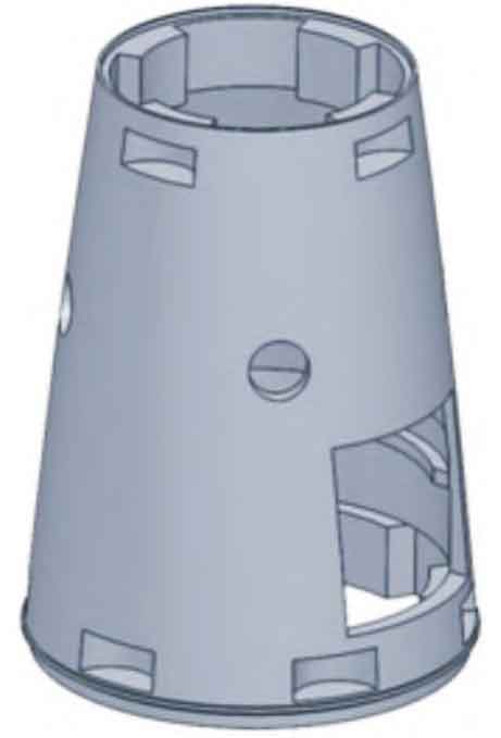
The three-dimensional model of the aluminum alloy cabin product is shown in Figure 1, with external dimensions of φ 336.08 mm x 455 mm, with a minimum wall thickness of 2 mm and a maximum wall thickness of 37 mm. The overall structure is a rotating body, with 4 in the middle of the product φ A 45 mm circular window with two square windows, one large and one small, with a designed weight of 12.07 kg. The upper, middle, and lower parts have thicker walls, while the rest have thinner walls. This structure can cause the product to solidify in segments during the low-pressure casting solidification stage, and cannot solidify in sequence. The thick and large hot sections cannot be fully filled, which can easily cause low-pressure casting defects such as porosity and shrinkage holes. Therefore, the design of the pouring system for this product needs to consider providing sufficient shrinkage to the hot spot area.
1.3 Determination of casting pouring system scheme
Select low-pressure casting and casting process. The inner cavity of the product belongs to a semi closed structure, and the metal core cannot be demolded. Therefore, a trial production method is adopted by combining the coated sand core and the metal core. After the product is demolded, the coated sand core is removed to obtain the product blank.
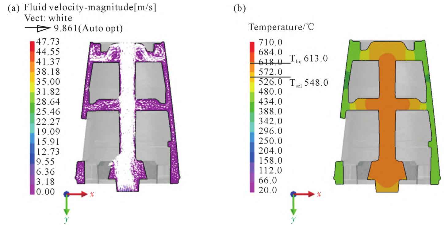
Comprehensively analyze the product structure and equipment characteristics, design the blank and pouring system of the product, design the processing allowance of the product based on the product size, and consider the shrinkage situation of the thick parts of the product to ensure the sequential solidification of the product pouring process. The pouring system is designed as a stepped feeding inner gate based on the product structure, feeding from three parts: top, middle, and bottom. The gate is designed inside the sand core, and the aluminum liquid can pass through the inside of the sand core. The sand core can also provide insulation for the aluminum liquid, as shown in Figure 2. After the completion of the pouring process design, numerical simulations were conducted on the flow field and solidification temperature field of the product blank melt using ProCAST casting simulation software. Analysis of the flow field showed that after the melt entered the mold cavity from the gate, it quickly filled from bottom to top, and the aluminum liquid filled smoothly, without turbulence, with an overall uniform flow rate; From the temperature field, it can be seen that during the solidification stage, the center temperature of the casting is relatively high, and the temperature from the center to the outer wall decreases in sequence, which is in line with the solidification sequence of the casting. The pouring system can provide maximum hot spot shrinkage for the casting. The results show that using this pouring system for production, the fluid filling is stable, without splashing, and the temperature field meets the requirements of casting solidification sequence, which can ensure that the hot spot area of the product is fully compensated without shrinkage porosity or shrinkage defects, as shown in Figure 3.
1.4 Layout of Demoulding Top Rod
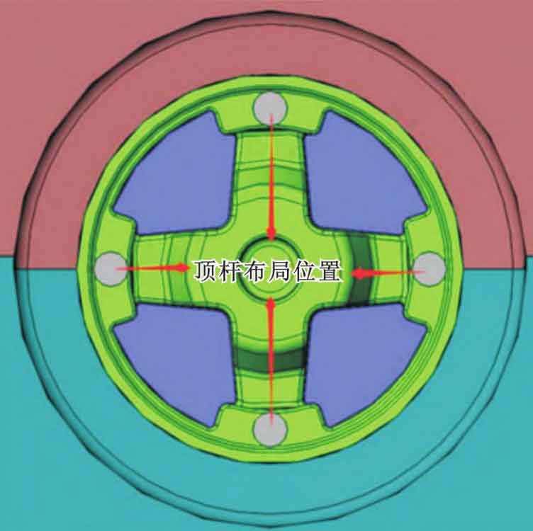
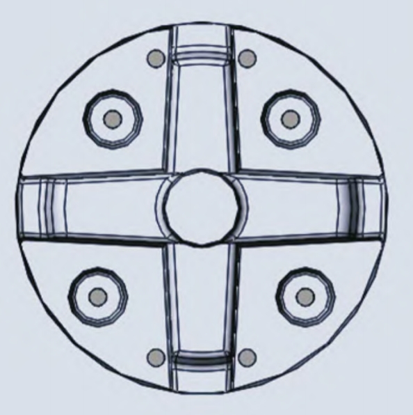
Due to the large volume and mass of the product, how to smoothly remove the blank from the metal mold will directly affect the continuity of production. Therefore, the layout of the top rod and the design of the draft angle of the product blank are extremely important. The metal mold of this product belongs to the four opening structure of upper, lower, left, and right. During the production process, the left and right cavities need to be opened first, and then the upper and lower cavities need to be opened. The demolding process needs to ensure that the product blank remains in the upper cavity of the metal mold after the upper and lower cavities are opened, and then demoulded through the top material mechanism. This requires setting a reasonable draft angle for the metal mold to ensure that the product blank and sand core can be brought to the upper cavity without falling off after the upper cavity is opened, Then the product blank will smoothly detach from the upper cavity. Due to the rotating structure of the product, the layout of the top rod is designed in a symmetrical position, as shown in Figure 4.
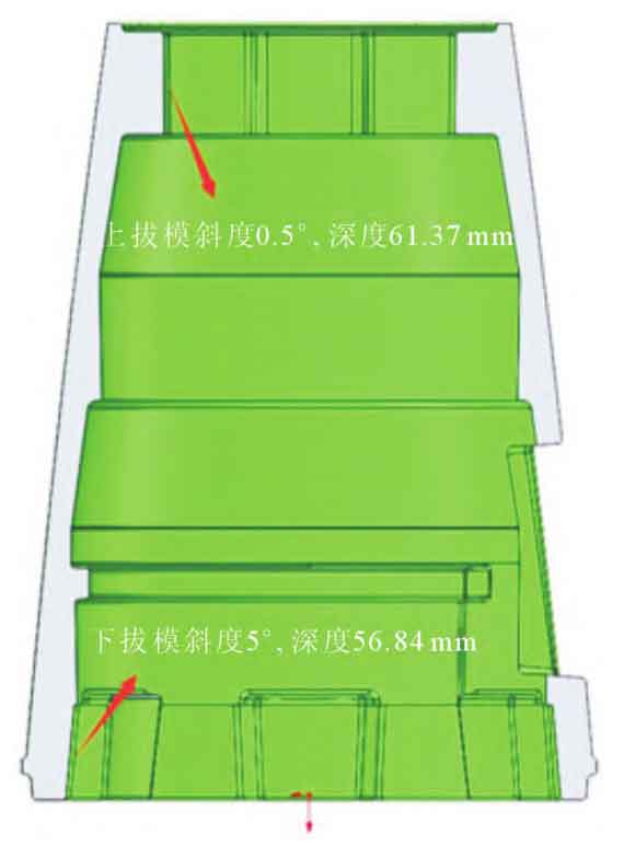
For the quality analysis of the product’s blank and sand core, sufficient clamping force is required in the upper cavity to remove the blank and sand core from the lower cavity and leave them in the upper cavity. The lower cavity needs to minimize the clamping force as much as possible, reduce the upward movement resistance of the casting during mold opening, to ensure normal mold opening and material removal. Analyzing the product structure, the depth of the upper model cavity is 61.37 mm, and the depth of the lower model cavity is 56.84 mm. In order to ensure a certain degree of clamping force and smooth demolding, based on previous mold trial experience, if the draft angle is set to 0, it will cause too much clamping force and the blank cannot be demolded smoothly. Therefore, it is necessary to provide the necessary draft angle for the upper model cavity within a certain range. Therefore, the draft angle for the upper model cavity is set to 0.5 °, and the draft depth is 61.37 mm; To reduce the clamping force of the lower model cavity and minimize machining allowance, the draft angle of the lower model cavity is set to 5 ° and the draft depth is 56.84 mm. The clamping force of the lower model cavity is reduced, as shown in Figure 5. After the product blank is opened, it is left in the upper model cavity, and then separated from the upper model cavity by the top material mechanism to achieve smooth material removal.
1.5 Process parameter settings
Due to the height of the product being 480 mm, the middle runner is φ 53 mm, the wall thickness of the product blank is uneven, and the aluminum liquid flows from the middle to the outer circle during filling. How to ensure the smooth and turbulent filling process of the aluminum liquid will determine whether the product blank is qualified after processing. Therefore, setting reasonable pouring parameters is an important link to ensure the quality of the product is qualified. By setting different filling parameters for numerical simulation, the flow field during different filling parameters was compared, and the smoothness of the aluminum liquid flow process was observed. Finally, a more reasonable process parameter was determined. The results show that when the temperature of the aluminum liquid is 700 ℃, the mold temperature is 320 ℃, and the filling and pressurization speed is 0.000 8 MPa · s-1, the aluminum liquid filling is the most stable. The optimal low-pressure pouring process parameters for the aluminum alloy cabin obtained through numerical simulation are shown in Table 1.
| Process parameters | Pressure/MPa | Boosting speed/(MPa · s ^ -1) | Time/s | Aluminum liquid temperature/℃ |
| Ascending liquid | 0.020 0 | 0.002 0 | 10 | 700 |
| Filling type | 0.036 0 | 0.000 8 | 20 | 700 |
| Boosting | 0.060 0 | 0.002 4 | 10 | 700 |
| Maintaining pressure | 0.060 0 | — | 360 | 700 |
| Cooling | — | — | 260 | 700 |
| Production and Next Stage | — | — | 240 | 700 |
2. Defects in low-pressure casting and their solutions
2.1 Analysis of Defects in Low Pressure Casting
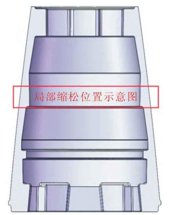
2.1.1 Local porosity of castings
100% X-ray inspection was conducted on the aluminum alloy cabin, and the inspection results showed that there was a certain degree of shrinkage and looseness inside the casting at the location shown in Figure 6. After analysis, this area is located in the middle of the product, with a wall thickness thicker than the upper and lower parts, and belongs to the hot spot area of the product. Due to the diameter of this area being φ 297.31 mm, with a wall thickness of 24.24 mm. The upper and lower wall thicknesses are both 14.27 mm, indicating a significant difference in size. According to the principle of sequential solidification, by setting process measures such as risers in thick areas where shrinkage may occur, the casting body can solidify before the riser area, achieving the effect of local shrinkage. Therefore, in the numerical simulation design process, a “I-shaped” sprue is designed in the middle of the area in advance to serve as a riser to supplement and shrink it. However, in actual production, it was found that due to the large diameter at the waist of the product, there is a problem of local shrinkage and looseness in the symmetrical position away from the gate inside the “I-shaped” gate.
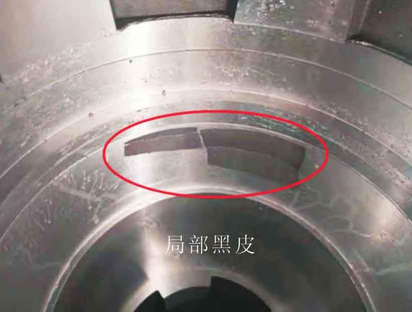
2.1.2 Local black skin appears on the inner wall of castings after processing
After heat treatment of the casting, it was found that local black skin appeared on the inner wall of the casting after processing, which was the area where the light could not be processed, and the position was not fixed, indicating that the inner diameter size of the product at the black skin was too large, and some of the rough dimensions could not meet the processing requirements of the drawing, as shown in Figure 7.
2.2 Solutions
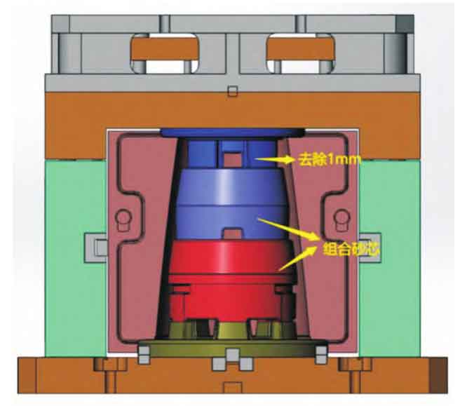
In response to the X-ray inspection results of castings and the problems encountered during processing, the solutions are as follows: ① For the local shrinkage porosity shown in Figure 6, the “one” shaped sprue is changed to a “ten” shaped sprue, as shown in Figure 8, to enhance the feeding system’s shrinkage of the product’s circular hot joint and solve the shrinkage porosity defect caused by insufficient feeding. ② Regarding the appearance of black skin images of different sizes on the inner wall of castings during the processing, the main reason is analyzed to be due to the bulging of the sand core during the mold closing process, causing local protrusions of the sand core, resulting in missing flesh on the inner wall of the casting. The thermal expansion coefficients of the metal mold and the sand core differ greatly, leading to changes in the fit gap between the metal mold and the sand core after heating up. To solve this problem, a caliper was used to measure the high temperature of the mold cavity under the heating state of the metal mold. By comparing the measured sand core dimensions, it was found that the size of the sand core placed in the heated mold was smaller than the height of the sand core, causing the sand core to bulge and crack during the mold closing process. Therefore, the size of the upper mold cavity of the metal mold was reduced by 1mm, and the mold closing gap between the upper and lower molds was increased to ensure that the metal mold will not crack the sand core during the mold closing process, as shown in Figure 9.
After production verification, changing the “one” shaped runner to the “ten” shaped runner in the middle waist annular hot joint area of the product can effectively compensate for the volume shrinkage during the solidification process of the middle waist annular hot joint, solve the shrinkage and loosening defects of the waist hot joint, and ensure that the internal quality of the product meets the requirements. Simultaneously increasing the fit gap between the metal mold and the sand core in the hot state can compensate for the interference fit caused by the different shrinkage ratios of the metal mold and the sand core in the hot state, and solve the problem of exceeding the product inner wall size caused by the fracturing of the sand core by the metal mold closing.
3. Conclusion
(1) According to the characteristics of the product structure, the draft angle of the upper model cavity is set to 0.5 °, the draft depth is 61.37 mm, the draft angle of the lower model cavity is 5 °, and the draft depth is 56.84 mm. When opening the mold, it can ensure that the blank and sand core are brought to the upper mold through the feeding mechanism to achieve smooth demolding, ensuring continuous production.
(2) In the low-pressure casting process of aluminum alloy cabin, when the temperature of the aluminum liquid is 700 ℃, the mold temperature is 320 ℃, and the filling and pressurization speed is set to 0.000 8 MPa · s-1, the aluminum liquid filling is the most stable.
(3) Measuring dimensions in the hot state of a metal mold can truly reflect the fit gap between the mold and the sand core, avoiding product inner wall dimensions exceeding the tolerance caused by mold thermal expansion and sand core cracking during production.